Sm series, General pump – General Pump SM Owners Manual User Manual
Page 13
GENERAL PUMP
A member of the Interpump Group
SM SERIES
Page 13
9.4 Hydraulic Connections
To isolate the plant from the vibrations produced by the pump, we recommend building the first section of hose
adjacent to the pump (for both intake and outlet) with flixible hose. The solidity of the intake section must be enough to
prevent deformation caused by the depression produced by the pump.
9.5 Pump Supply
SM pumps require a positive water head (NPSH
r
) of between 75-100 PSI (5-7 Bar) at the pump head entrance. The
booster supply pump must have a flow rate at least double that of the rated flow rate of the plunger pump, and a
minimum pressure of 75 PSI (5 bar). These supply conditions must be respected for any and all working regimes. The
booster pump must be run independent of the plunger pump.
The booster pump must always be started before the plunger pump. We recommend
installing a pressure regulator on the supply line downstream of the filters, to protect the pump.
9.6 Suction Line
For the pump’s correct operation, the suction line must have the following characteristics:
1. Minimum internal diameter as indicated in the diagram in paragraph 9.8 and in any case equal or greater
than the pump head’s value. Along the duct, avoid localized diameter reductions that may cause pressure
drops with subsequent cavitation. Absolutely avoid 90
o
elbows, connections with other hoses, bottlenecks,
counter-slopes, upside down “U” shaped curves, “T” connections.
2. With a layout that is set in such a way to prevent cavitation.
3. It should be perfectly airtight, and built in a way that guarantees perfect sealing over time.
4. Avoid pump emptying when stopping (even partial emptying).
5. Do not use hydraulic fittings, 3 or 4 way fittings, adapters, etc., since they may hinder the pump’s
performance.
6. Do not install Venturi tubes or injectors for detergent intake.
7. Avoid the use of standing valves, check valves, or any other type of one-way valves.
8. Do not connect the by-pass line from the valve directly to the pump suction line.
9. Provide appropriate baffle plates inside the tank in order to avoid water flows coming from both the by-pass
and feeding lines may create turbulance near the tank’s outlet port.
10. Make sure that the suction line is perfectly clean inside before connecting it to the pump.
11. The pressure gauge for checking booster pressure must be installed near the plunger pump’s outlet port, and
always downstream from the filters.
Ref 300893 Rev.A
06-12
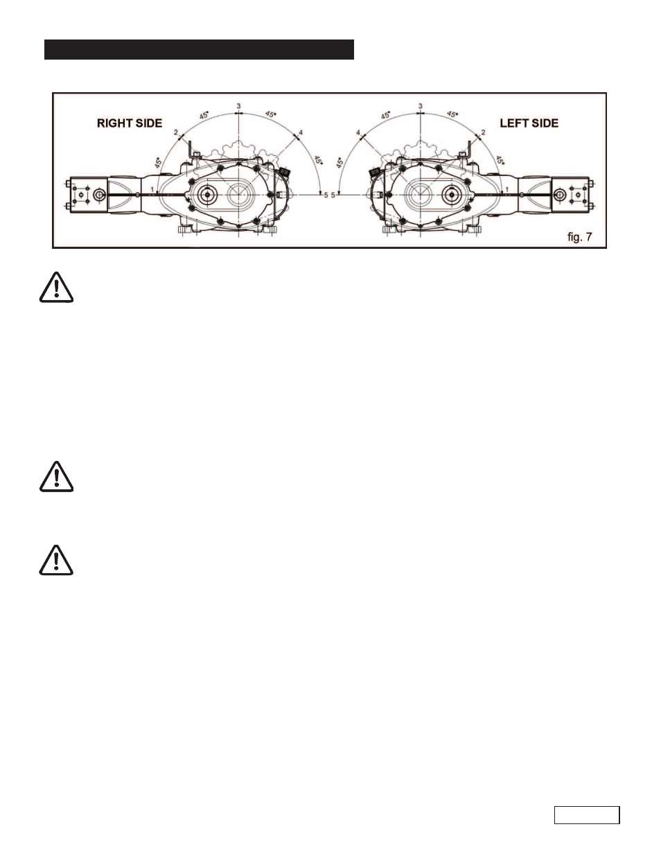
The reducer’s position may be changed only by specialized and authorized personnel by carefully
following the instructions in the repair manual.