Owner service, Always obey all safety warnings, Instructions – Farm Star SRTC-406A User Manual
Page 20: Attachment, Driveline length check procedure, Continued), Warning, Lubrication information, Routine maintenance
19
24
ATTACHMENT
The cutter is shipped partially assembled. Assembly will
be easier if components are aligned and loosely assem-
bled before tightening hardware. Recommended torque
values for hardware are located on page 27.
Select a suitable working area. Refer to illustrations,
accompanying text, parts lists and exploded view
drawings.
Complete check lists on page 21 when assembly is
complete.
Position cutter flat and cut the nylon straps that are
holding all loose parts to the cutter.
Rotate the “A” frame hitch forward and connect lift arms
and toplink.
Attach the two linkage lift straps to the cutter deck
(behind the gearbox) and to the bolted connection at the
top of the “A” frame has a moveable center link – so
tighten nylock nut only until excess looseness is
removed.
Most swinging drawbars will have to be moved to a
forward position or removed. Check the tractor swing-
ing drawbar for interference with the front of the cutter
before attempting to lift the cutter with the 3-pt. hitch.
Tractor lift arm stabilizer bars or sway blocks must be
used to control side movement of the cutter. DO NOT
CONNECT THE PTO DRIVELINE AT THIS TIME.
Check your lift arm hydraulic controls. Be sure the
hydraulic 3-pt. hitch control is in the float position and the
draft control is turned off.
Adjust lower lift arm(s) to level cutter right to left. Refer
to tractor operator’s manual for instructions.
Cutting height is controlled with tractor 3-point arms,
and rear tailwheel adjustment.
DRIVELINE LENGTH CHECK
PROCEDURE
In some cases it will be necessary to shorten the PTO
assembly to match your particular tractor. The following
procedure should be used:
1. Raise the tractor 3-pt. hitch so the input shaft of the
cutter gearbox is in line with the PTO shaft on the
tractor. Shut down tractor, leaving cutter in position of
shortest distance between shafts. SECURELY
BLOCK CUTTER IN POSITION.
INSTRUCTIONS
(continued)
Figure 2.
Figure 3.
NOTE: The use of a PTO over-running clutch or exten-
sion could require that the PTO driveline be shortened a
considerable amount. If this is done, the driveline halves
may separate when the cutter is lowered to the ground or
when operated on rough ground.
1. Raise and lower the cutter to determine position with
greatest distance between the PTO shaft and gearbox
input shaft. Shut tractor off, leaving cutter in position
of greatest distance between shafts. SECURELY
BLOCK CUTTER IN POSITION.
2. Hold driveline sections parallel to each other and
check for minimum 6” (15cm) overlap. If driveline
has been marked for cutting, overlap will be the
distance between the two marks. If driveline has less
than minimum overlap, do not use. Contact authorized
dealer.
WARNING!
Before operating the cutter, check to make sure the
driveline will not bottom out or become disengaged.
2. Pull driveline apart. Attach outer (female) section to
tractor PTO shaft. Pull on driveline section to be sure
that yoke locks into place.
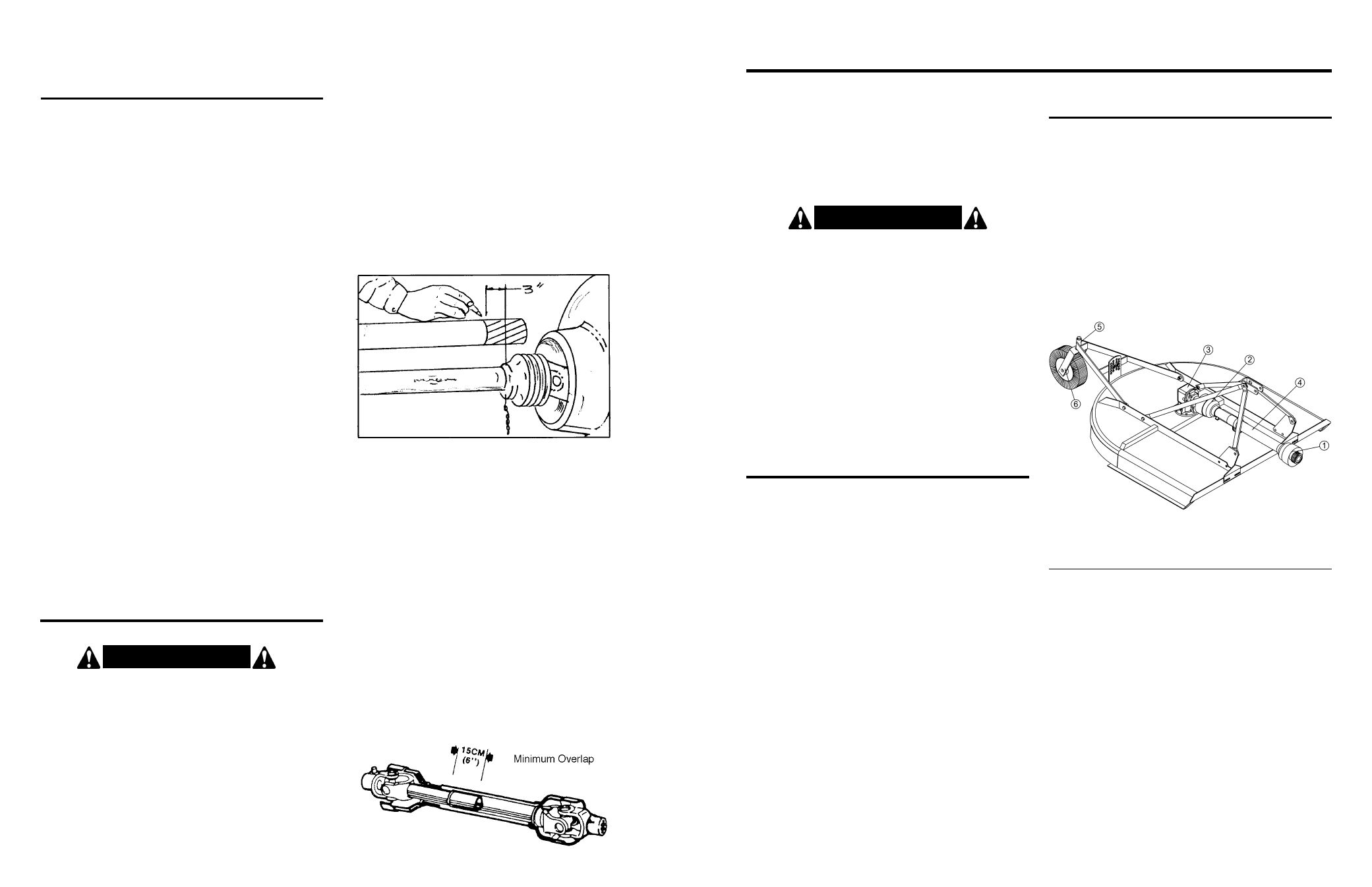
3. Hold driveline sections parallel to each other to
determine if too long. Each section should end
approximately 3” (76mm) short of reaching universal
joint shield on opposite section. If too long, measure
3” (76mm) back from universal joint shield and mark
on opposite section (Figure 3). Do this for both sec-
tions. DO NOT CUT UNTIL STEPS 4 AND 5 ARE
CHECKED.
OWNER SERVICE
The information in this section is written for operators
who possess basic mechanical skills. Should you need
help, your dealer has trained service technicians
available. For your protection, read and follow all safety
information in this manual.
WARNING!
▲
▲ Lower cutter to ground or block securely, turn
tractor engine off, remove key and disconnect cut-
ter driveline from tractor PTO before performing
any service or maintenance.
▲
▲ Before working underneath, raise 3-pt. hitch to
highest position and block cutter securely.
Hydraulic system leakdown and failure of
mechanical or hydraulic system can cause equip-
ment to drop.
▲
▲ Keep all persons away from operator control area
while performing adjustments, service or mainte-
nance.
LUBRICATION INFORMATION
Figure 6 shows the lubrication points. The accompany-
ing chart gives the frequency of lubrication in operating
hours, based on normal conditions. Severe or unusual
conditions may require more frequent lubrication.
Do not let excess grease collect on or around parts,
particularly when operating in sandy areas.
Use an SAE 90W gear lube in gearbox.
Use a lithium grease of NO. 2 consistency with a MOLY
(molybdenum disulfide) additive for all locations. Be sure
to clean fittings thoroughly before attaching grease gun.
When applied according to the lubrication chart, one
good pump of most guns is sufficient. Do not over
grease.
Figure 6.
LUBRICATION CHART
REF NO.
DESCRIPTION
FREQUENCY
1
Front U-Joint
8 Hrs.
2
Rear U-Joint
8 Hrs.
3
Gearbox – Fill to proper level
Check Daily
4
Slip Joint
8 Hrs.
5
Tailwheel Swivel
8 Hrs.
6
Tailwheel
8 Hrs.
Daily lubrication of the PTO slip joint is necessary.
Failure to maintain proper lubrication can result in
damage to U-joints, gearbox, tractor PTO and/or cutter
driveline.
ALWAYS OBEY ALL
SAFETY WARNINGS!!
ROUTINE MAINTENANCE
DAILY CHECKS:
1. Check that all bolts, nuts, and screws are tight.
Checking the bolts and nuts on the blade beam
assembly is particularly important.
2. Check daily the level of the gearbox oil and top up to
the correct level. Check for gearbox oil leaks. It should
be noted that no warranty claim can be submitted on
a gearbox that has run dry. It is essential that the
gearbox is kept correctly filled with gearbox oil.
3. Grease the PTO shaft daily.
4. Check the wear on the blades. Sharpen them
routinely with an angle grinder or replace when worn
down too far. You should keep at least two sets of
blades, bolts, and nuts as spares for your cutter.
AT THE END OF YOUR CUTTING SEASON:
1. Drain and change the oil in your gearbox.
2. Check and replace, where necessary, blades, bolts,
nuts, or bushings, on the machine.
3. Clean machine and touch up any rust spots that may
have appeared.
4. Replace any safety signs if damaged.
5. Store cutter in clean, dry location.