Ub-645 blade, Ub-745 blade – Farm Star UB-850-T User Manual
Page 11
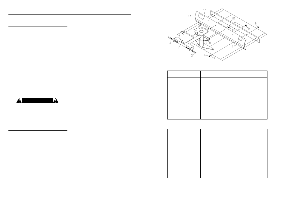
10
5
REF.
PART
NO.
NO.
NO.
DESCRIPTION
REQ.
1
346601
3 Pt. Mount Frame
1
2
590108
Lift Pin Assembly (AK-578)
2
3
350030
Adjustment Pin
1
4
2500003
Full Hex Nut
1
/
2
” – 13NC
2
5
2502002
Spring Lockwasher
1
/
2
”
2
6
2500013
Full Hex Nut
5
/
8
” – 11NC
8
7
2502007
Spring Lockwasher
5
/
8
”
8
8
2503045
No. 3 Plow Head Bolt
5
/
8
” – 11NC x 1
1
/
2
”
6
9
2503179
No. 3 Plow Head Bolt
5
/
8
” – 11NC x 2”
2
10
350405
6 Ft. Cutting Edge
1
11
346612
6 Ft. Moldboard
1
12
2503004
Hex Head Bolt
1
/
2
” – 13NC x 1
1
/
2
”
2
13
101033
Decal – Caution, Safe Operating Practices
1
14
101052
Decal – Warranty Notice
1
UB-645 BLADE
REF.
PART
NO.
NO.
NO.
DESCRIPTION
REQ.
1
346601
3 Pt. Mount Frame
1
2
590108
Lift Pin Assembly (AK-578)
2
3
350030
Adjustment Pin
1
4
2500003
Full Hex Nut
1
/
2
” – 13NC
2
5
2502002
Spring Lockwasher
1
/
2
”
2
6
2500013
Full Hex Nut
5
/
8
” – 11NC
9
7
2502007
Spring Lockwasher
5
/
8
”
9
8
2503045
No. 3 Plow Head Bolt
5
/
8
” – 11NC x 1
1
/
2
”
6
9
2503179
No. 3 Plow Head Bolt
5
/
8
” – 11NC x 2”
3
N/S
350029
7 Ft. Cutting Edge
1
N/S
346701
7 Ft. Moldboard
1
12
2503004
Hex Head Bolt
1
/
2
” – 13NC x 1
1
/
2
”
2
13
101033
Decal – Caution, Safe Operating Practices
1
14
101053
Decal – Warranty Notice
1
UB-745 BLADE
MODEL NO.
UB-645
SHOWN
T R A C T O R R E Q U I R E M E N T S
A N D P R E PA R AT I O N
A S S E M B LY A N D M O U N T I N G
The UB Series Rear Blades will fit most Category I
tractors equipped with a standard 3-point hitch. These
blades are designed for use on tractors up to 50
horsepower. For use on larger tractors, extra care is
required and it is strongly suggested that purchasing a
heavier rear blade be considered.
Check the tractor’s 3-point hydraulic lift system. It
should operate up and down smoothly and hold its
position when set. Refer to your tractor owner’s manual
or dealer for any adjustments necessary to put the 3-
point hydraulic lift system in good working order. (I&T
shop manuals will list most specifications and adjustment
instructions – available from most farm equipment
dealers.)
Tractor should be equipped with stabilizer bars,
adjustable sway chains, or sway blocks to keep the
implement from swinging side to side.
Smaller size tractors may need front counter weights to
counter-balance the weight of the implement.
It is recommended that the tractor be equipped with a
Rollover Protection System (ROPS) and a seat belt that
is used.
It is suggested that you mount the main frame on the 3-
point hitch of your tractor before assembling the blade as
follows:
1. Lower the 3-point hitch on your tractor to facilitate
mounting of the main frame of the blade to the tractor.
2. Insert the lift arm pins on the main frame into the ball
sockets in the lift arms of the tractor 3-point hitch. Pin
in place with linch pins (not furnished).
3. Attach the mast of the main frame to the tractor by
installing the tractor center (or top) link with a top link
pin (not furnished). Pin in place with a linch pin (not
furnished).
The main frame of the blade is now installed on the
tractor. You are ready to proceed with assembling the
moldboard and cutting edge assembly to the main frame
as follows:
UB-645 BLADE
(6 ft. Moldboard mounting instruction.)
1. Remove the two center plow bolts from the moldboard
assembly.
2. Position the moldboard assembly in front of the spin-
dle assembly and place the two center plow bolts
through the moldboard assembly and into the corre-
sponding holes in the lower moldboard bracket on the
spindle assembly.
3. Place the two
1
/
2
” x 1
1
/
2
” hex head bolts provided
through the two center holes at the top of the
moldboard assembly into the corresponding holes on
the upper moldboard bracket on the spindle assembly.
(NOTE: The moldboard assembly may be positioned
in the center, 12” to the right, or 12” to the left, accord-
ing to the setting desired.)
4. Tighten all bolts securely.
UB-745 BLADE
(7 ft. Moldboard mounting instruction.)
1. Remove the three center plow bolts from the mold-
board assembly.
2. Position the moldboard assembly in front of the spin-
dle assembly and place the three center plow bolts
through the moldboard assembly and into the corre-
sponding holes in the lower moldboard bracket on the
spindle assembly.
3. Place the two
1
/
2
” x 1
1
/
2
” hex head bolts provided
through the two center holes at the top of the moldboard
assembly and into the corresponding holes on the
upper moldboard bracket on the spindle assembly.
(NOTE: The moldboard assembly may be positioned
in the center, 12” to the right, or 12” to the left, accord-
ing to the setting desired.)
4. Tighten all bolts securely.
UB-650-T, UB-750-T, AND UB-850-T BLADES
(6 ft., 7 ft., & 8 ft. Moldboard mounting instructions.)
1. Place the two tilt adjustment bolts into the moldboard
brackets (one on each end).
2. Position the moldboard against the spindle mounting
bracket, with the two tilt adjustment bolts extending
through the radial slots in the spindle mounting bracket.
3. Place the tie plates over the tilt adjustment bolts.
4. Tighten all bolts securely.
5. In order to tilt the moldboard simply loosen the nuts
on the tilt adjustment bolts and pivot to the desired
angle, then retighten the nuts.
NOTE: Always use the tractor anti-sway bars, blocks, or
chains to prevent blade side-sway. This is a must when
using the blade in a reverse position.
Your Rear Mounted Blade is now assembled and
mounted on your tractor. It is ready to go to work for you.
I N S T R U C T I O N S
Be sure your tractor is in good condition and
properly equipped with counter weights. Read all the
safety precautions and make sure all tractor
operators are familiar with the safety rules of tractor
operation.
C A U T I O N !