A. platform cornering – Fairbanks Portable Axle Load Scale User Manual
Page 9
A. Platform Cornering
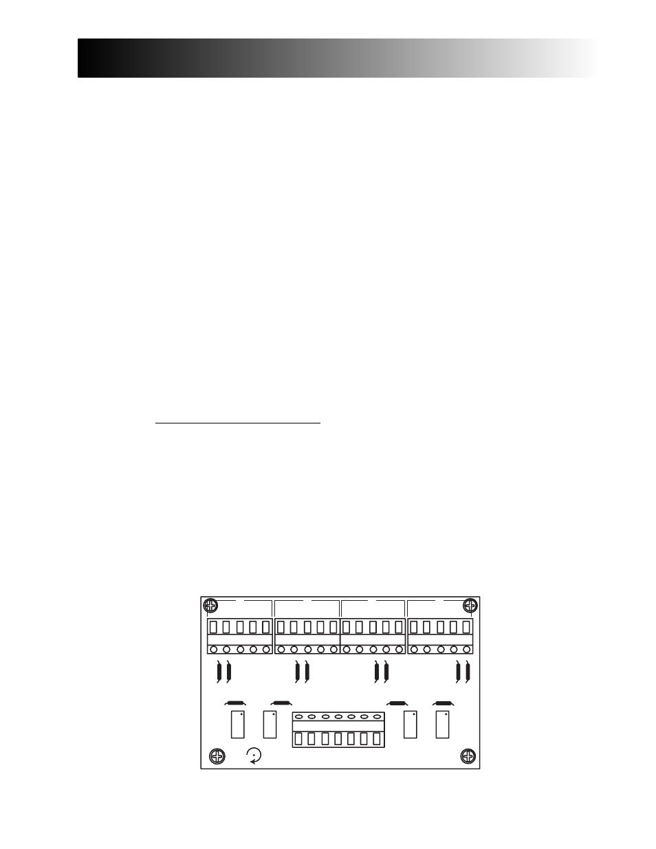
Analog Interface (Junction Box 67171):
1.
Adjust the analog indicator to the platform. First, ensure all corners are within
one (1) division of each other at 25% of rated capacity. Follow the appropriate
indicator service manual for indicator calibration.
a.
Perform a course platform calibration close to the actual weight.
b.
Identify the platform corner numbers.
c.
Place a concentrated weight (25% of platform capacity) on corner 1. Move it
to corner 2, corner 3 and corner 4, noting the displayed reading on each
corner.
d.
If corners require adjustment: Place the concentrated weight on the corner
displaying the lowest weight and use the appropriate potentiometer to
change the displayed weight to read the same as the highest reading by
turning the potentiometer clockwise (CW). Repeat this procedure while
rechecking all corners until there are no errors. Perform a zero reference
check with a unloaded platform, then repeat the corner test to ensure all
readings are the same before proceeding.
04/05
9
50784 Issue 1
Section 33: Calibration
4
4
3
3
2
2
1
1
+ SIG
- SIG
- SEN
- EXC
+ SEN
- EXC
SHLD
+E -E SH -S +S
+E -E SH -S +S +E -E SH -S +S
+E -E SH -S +S
96141