Load cell assembly detail, Top view of cover plate – Fairbanks Portable Axle Load Scale User Manual
Page 7
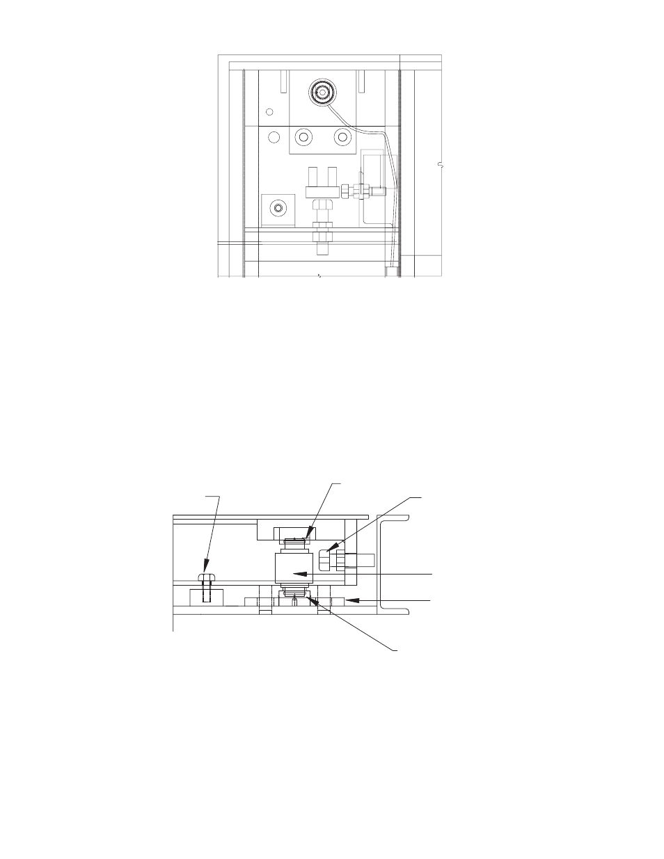
7.
Remove the shipping bolts in each corner.
8.
Adjust the checking bolts to a
1
/
16
” to
1
/
8
” clearance.
9.
Verify all of the load cells are plumb, square and level. Correct if necessary.
10. If ramps are part of the installation, they should be located and installed at this
time.
04/05
7
50784 Issue 1
TOP VIEW OF COVER PLATE
50784-2
50784-1
LOAD CELL
ASSEMBLY DETAIL
ADJUST BUMPER BOLT TO 1/16" - 1/8"
O-RING IN EACH
RECEIVER CUP
UPPER CUP
LOAD CELL
LOWER BASE PLATE
HOLD DOWN BOLT
FOR SHIPPING
See also other documents in the category Fairbanks Scales:
- 6001 Delta Series Analog Platforms (20 pages)
- NexWeigh (80 pages)
- 5001 Series QuickSilver IS (25 pages)
- 5000 Series Bench Scale Platforms (22 pages)
- Series II Bench Scales (14 pages)
- Series III Bench Scales (15 pages)
- SCB-R9000-B Series Ultegra Baggage (19 pages)
- SCB-R9000-14U Ultegra Bench Scale (16 pages)
- SCB-R9050 Series Ultegra MAX (17 pages)
- Ultegra Junior Bench Scale (18 pages)
- 1129 SERIES Dual Platform Counting Scale (50 pages)
- OMEGA SERIES COUNTING SCALE (62 pages)
- AN Series Fairbanks Access Solutions (120 pages)
- FB2550 DAT SERIES DRIVER ACCESS TERMINAL (159 pages)
- Aegis Xtreme-Duty Floor Scale (32 pages)
- Aegis Transport Scale (32 pages)
- Aegis Lift Deck (26 pages)
- Aegis Industrial Mild Steel (30 pages)
- Aegis Heavy Capacity PLF-6200-H Series (18 pages)
- Aegis Drum Scales (34 pages)
- Aegis Coil Scales (42 pages)
- BlueLineFS Scale System (24 pages)
- 3300 Reliant Series Floor Scale (19 pages)
- 3500 Series Yellow Jacket (26 pages)
- FB1100 Series Yellow Jacket FS Package (30047, 30048) (70 pages)
- FB2250 Series Yellow Jacket FS Package (94 pages)
- IM 6000 Series In-Motion Scale System with FB3000 (25 pages)
- Ultegra Health Scale (10 pages)
- 27135 TeleWeigh with Bluetooth (18 pages)
- 26889 Slimline Health Scale (16 pages)
- BPP1000 Portable Platform Scale (22 pages)
- 1155 SERIES Portable Utility SCALE WITH THE FB2255 (32 pages)
- 1124 Portable Platform Scale (16 pages)
- 1100 Series Portable Utility Scale with Rechargeable battery-powered FB1100 ABS (22 pages)
- H90-5200-A Digital Instrument (60 pages)
- FB2255 Series Instrument PC2255 PC Software Utility Program (79 pages)
- FB3000 Highway System Application (96 pages)
- FB2550 SERIES (186 pages)
- FB6001 INSTRUMENTATION (83 pages)
- FB3000 II Operators Manual (68 pages)
- FB3000 Inbound/Outbound Program Operators Manual (40 pages)
- FB3000 Kernel Program Operators Manual (69 pages)
- H90-3052-D Fairbanks Scales (19 pages)
- 2800 Series Intrinsically Safe Instrument (73 pages)
- 12-1492 - 12-1496 A.A.R. Combination Railroad Track/MTS (59 pages)