Approved safety barriers, Safety earth, Apparatus located in the hazardous area – Fire Fighting Enterprises Talentum IR3 Flame Detector User Manual
Page 8
8
Galvanically Isolated Barrier
Galvanically isolated barriers (also know
as transformer isolated barriers) differ
from conventional shunt zener barriers in
that they provide electrical isolation
between the input (safe area) and the
output (hazardous area). This is achieved
by the use of a D.C./D.C. converter on the
input side, which is connected to the
hazardous area through a voltage and
power limiting resistor/zener combination
similar to a conventional barrier.
The galvanic isolation technique means
that the circuit does not need a high
integrity (safety) earth and that the
intrinsically safe circuit is fully floating.
Earth leakage problems for control and
indicating equipment are therefore
eliminated if this type of interface is used.
Galvanically isolated barriers are widely
used with conventional flame detector
systems. If the system is of an
addressable type with signal pulses on
the supply lines then the response time of
most standard barriers will be too slow to
allow their use. In these applications
special galvanically isolated barriers are
required that can freely transmit the
required protocol pulses without
introducing severe voltage drops. These
interfaces are available as single or dual
channel versions and are recommended
for any application in which direct earth
connections are not acceptable.
The galvanically isolated barrier is a two-
wire device which does not need an
external power supply. Current drawn
from the detector supply connections by
the barrier itself is less than 500µA.
Approved Safety Barriers
For systems a generic specification for the
barriers is as follows.
Any non-isolating zener safety barrier
certified and approved to meet the ATEX
Directives or CENELEC / IEC standards.
ATEX group and category
II (1) G
CENELEC / IEC marking [Ga Ex ia] II C
(associated apparatus)
Having the following or lower output
parameters.
Max. output volts
U
o
: =
28V
Max. output current I
o
: =
93mA
Max. output power P
o
: =
0.65W
A number of barriers meet this
specification and examples are given
below.
Table 5 Examples of permitted safety barriers/isolators
Supplier
Type
Channels Technique
Certificate
Pepperl & Fuchs Ltd.
77 Ripponden Road,
Oldham,
Lancs. OL2 8PF
UK
www.pepperl-fuchs.com
Z728
Z779
KFD0-CS-Ex1.51
KFD0-CS-Ex2.51
1
2
1
2
300
Ω Barrier
300
Ω Barrier
Isolator
Isolator
BAS01ATEX7005
BAS01ATEX7005
BAS98ATEX7343
BAS98ATEX7343
MTL
Power Court,
Luton,
Bedfordshire LU1 3JJ
UK
www.mtl-inst.com
MTL7028+
MTL7728+
MTL7779+
MTL7706+
1
1
2
1
300
Ω Barrier
300
Ω Barrier
300
Ω Barrier
Active 300
Ω
4-20mA O/P
BAS99ATEX7285
BAS01ATEX7217
BAS01ATEX7217
BAS01ATEX7217
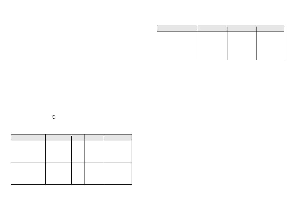
9
The terminal parameters for the isolators and barriers permitted by the system certificate are: -
Type
Uo
Io
Po
Z728
Z779
KFD0-CS-Ex1.51
KFD0-CS-Ex2.51
MTL7028+
MTL7728+
MTL7779+
MTL7706+
28V
28V
25.2V
25.2V
28V
28V
28V
28V
93mA
93mA
93mA
93mA
93mA
93mA
93mA
93mA
650mW
650mW
585mW
585mW
650mW
650mW
650mW
650mW
Table 6 Permitted isolator and barrier terminal parameters.
The above barriers and isolators are to be supplied from apparatus which is unspecified except that
it must not be supplied from nor contain in normal or abnormal conditions a source of potential with
respect to earth in excess of 253 volts r.m.s. or 253 volts d.c.
Safety Earth
Single channel and star connected A.C.
safety barriers must be connected to a high
integrity earth by at least one and preferably
two copper cables, each of cross sectional
area of 4mm² or greater. The connection
must be such that the impedance from the
connection point to the main power system
earth is less than one ohm.
Intrinsically safe circuits in the hazardous
area should be insulated from earth and
must be capable of withstanding a 500V
RMS A.C. test voltage for at least one
minute.
When using armoured or copper sheathed
cables, the armour or sheath is normally
isolated from the safe area busbar.
Apparatus Located in the Hazardous Area
The following may be located in the hazardous area: -
•
One or two 016XXX Flame Detectors to certificate BAS02ATEX1001 and coded
Ga Ex ia IIC T4.
•
An optional single resistor that has a surface area of greater than 20mm² may be
connected in the fault relay circuit.