Cables, Maximum cable lengths – Fire Fighting Enterprises Talentum IR3 Flame Detector User Manual
Page 6
6
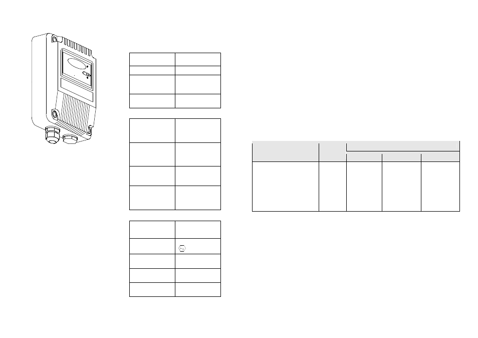
Intrinsically Safe Flame Detector
(Alloy Housing)
Fig. 2
The flame detectors respond to light emitted
from flames during combustion.
The detectors discriminate between flames
and other light sources by responding only to
low frequency flickering produced by flames
(typically 1 to 15Hz). The detectors ignore
fixed light sources and rapidly flickering
illumination predominantly produced by
lighting.
The flame flicker techniques have the
advantage of still allowing the detection of
flames through a thin layer of oil, water
vapour, ice or dust. This makes these
detectors particularly useful in industrial
applications.
Full details of the principles of operation,
electrical description, and other detailed
technical data are published in the products
individual data sheet.
Technical Data
Mechanical
Housing Material:
See figure 2
Die Cast Zinc Alloy
Housing Colour:
Blue (typical)
Housing
Dimension:
(Excluding Mounts)
Height = 142mm
Width = 108mm
Depth = 82mm
Cable Gland
Entries:
2 X 20mm
Electrical
Supply In:
Voltage
Current
Polarity sensitive
Terminals 1(+) & 2(-)
14 to 30Vdc
2 to 30mA
See data
sheet for detail
Optional Input:
Voltage
Current
Polarity sensitive
Terminals 3(+) & 4(-)
14 to 30Vdc
40µA
typ. @
24V IN
Optional Output:
Voltage
Internally Limited
Current
Terminals 3(+) & 4(-)
0V to
Supply In (O/C)
2.4
mA typ
.
Optional Relays
Contact Ratings:
Resistive
Voltage
Loads Only
Current
Terminals 3 to 8
30Vdc. Max.
1 Amp. Max.
Environmental
Operating Ambient
Temperature:
Check detector limits
-20°C to +40°C(T4)
ATEX
Approval Category
II 1 G
CENELEC / IEC
Marking
Ga Ex ia IIC T4
Apparatus
Certificate Number
BAS02ATEX1001
System
Certificate Number
Baseefa08Y0078
IR S
ENS
OR
FIRE
11
Cables
The interconnections to any of the four intrinsically safe circuit configurations shown on the system
drawings may be achieved by separate cables or by separate circuits within a Type A or Type B
multicore cable (clause 8 of EN 60079-25) subject to the following:
•
Each circuit is to be individually screened within a Type A multicore cable.
•
The peak voltage of any circuit within a Type B multicore cable must not exceed 60V, and
the cable must be effectively protected against damage.
Only insulated cables meeting the requirements of clause 8 of EN 60079-25 shall be used.
The installation of the system must be done in accordance with EN 60079-14.
Maximum Cable Lengths
The following cable types are considered to be Type B cables suitable for use in the Flame Detector
system. The maximum permitted cable lengths when using these cables is shown below:
Cable Type
Core
Maximum Cable Length
IIC
IIB
IIA
AEI Cables 6193Y (BS6004)
Prysmian FP200Gold 1.5mm²
(Formally Pirelli)
AEI Cables M.I. ref 7H1.5
AEI Cables M.I. ref 2L1.5
3
2 or 4
7
2
379m (620m)
313m (513m)
213m (350m)
146m (240m)
5.00km(5.00km)
5.00km(5.00km)
3.45km(3.59km)
2.37km(2.46km)
5.00km(5.00km)
5.00km(5.00km)
5.00km(5.00km)
5.00km(5.00km)
Table 8 Examples of maximum permissible cable lengths – [Two detectors (Single detector)]
When only a single Flame Detector Power Supply terminal pair (terminals 1 & 2) or Remote Test
terminal pair (terminals 3 & 4) is connected to a single circuit from the barrier or isolator listed in
table 5 then the capacitance may be increased to the values shown in brackets. The increase in
cable capacitance is not affected by the number of Flame Detectors Fire Relay connect terminal
pairs (terminals 5 & 6) or Fault Relay contact terminal pairs (terminals 7 & 8) connected to a single
circuit.