Selection of cable glands, Enclosure details, Flameproof products – Fire Fighting Enterprises Talentum IR3 Flame Detector User Manual
Page 5
8
15
0
146
86
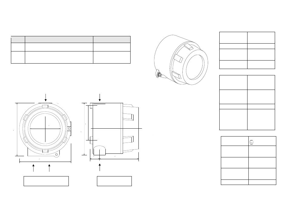
UNITS: mm.
27
15
0
110
10
0
.
Selection of Cable Glands
Application of barrier glands certified and approved to meet EN 60079-14 for Thermo Plastic,
Thermosetting and Elastomeric Cables. The external cables and glands used for high
temperature application must be compatible with the temperature.
Table 5 Examples of barrier glands
Enclosure Details
Hazardous Area Type
Gland Method
1)
Zone 1, 2 21 & 22 Hazardous areas requiring IIC
apparatus
Exd Barrier Glands
mandatory
2)
Zone 2 & 22 Hazardous areas requiring IIA & IIB
apparatus.
Any Exd Gland permitted
Entry Thread Type – A1, 2 & 3
3 off – M20 x 1.5
Fixing Holes – B
2 off – M6 (8mm deep)
A1
A1
A2
A3
A2 & 3
B
B
5
Flameproof Products
Flameproof Flame Detector
(Alloy Housing)
Fig. 1
The flame detectors respond to light emitted
from flames during combustion.
The detectors discriminate between flames
and other light sources by responding only to
low frequency flickering produced by flames
(typically 1 to 15Hz). The detectors ignore
fixed light sources and rapidly flickering
illumination predominantly produced by
lighting.
The flame flicker techniques have the
advantage of still allowing the detection of
flames through a thin layer of oil, water
vapour, ice or dust. This makes these
detectors particularly useful in industrial
applications.
Full details of the principles of operation,
electrical description, and other detailed
technical data are published in the products
individual data sheet.
Technical Data
Mechanical
Housing Material:
See figure 1
Copper Free
Aluminium Alloy
LM25
Housing Colour:
Red
Housing
Dimension:
(Excluding Mount)
Height = 150mm
Width = 146mm
Depth = 137mm
Cable Gland
Entries:
3 X 20mm
Electrical
Supply In:
Voltage
Current
Polarity sensitive
Terminals 1(+) & 2(-)
14 to 30Vdc
2 to 28mA
See data
sheet for detail
Optional Input:
Voltage
Current
Polarity sensitive
Terminals 3(+) & 4(-)
14 to 30Vdc
40µA
typ. @
24V IN
Power Up Time: 2 seconds
Relays
Contact Ratings:
Voltage
Current
Power
Resistive Loads Only
Terminals 5 to 8
30Vdc. Max.
1 Amp. Max.
30W Max.
Environmental
ATEX
Approval Category
II 2 G D
CENELEC / IEC
Marking
Ex d IIC T4 Gb
Ex tb IIIC T135°C Db
(Zone 1, 21, 2 & 22)
Ambient Temperature
Range:
Also
check detector data sheet.
Tamb -40°C to +125°C
Apparatus
Certificate
Numbers
Baseefa08ATEX0270
IECEx BAS08.0073
IP Rating
IP66