Theory of operation, Signal processing, Detector interior – Fire Fighting Enterprises Talentum UV/IR2 Flame Detector User Manual
Page 5: Electrical connections
5
Theory of Operation
8
The detector responds to low-frequency
(1 to 15 Hz.) flickering IR radiation emitted
from flames during combustion.
IR flame flicker techniques enable the
sensor to operate through a layer of oil,
dust, water vapour, or ice.
Most IR flame sensors respond to 4.3µm
light emitted by hydrocarbon flames. By
responding to 1.0 to 2.7µm light emitted
by every fire all flickering flames can be
detected. Gas fires not visible to the
naked eye e.g. hydrogen may also be
detected.
The dual (IR²) and triple (IR³) IR
photoelectric detectors, responding to
neighbouring IR wavelengths, enable it to
discriminate between flames and spurious
sources of IR radiation.
The combination of filters and signal
processing allows the sensor to be used
with little risk of false alarms in difficult
situations characterised by factors such
as flickering sunlight.
Signal Processing
The detector views the flame at particular
optical wavelengths. The more differing
optical wavelength signals available the
better the detector is at discriminating
between flames and false optical sources.
So although IR², IR³ and UV/IR² detectors
can detect similar sized flames at the
same distances, the UV/IR² detector will
give the greatest optical false signal
immunity as it has the most diverse
selection of optical wavelengths.
The detector processes the optical signal
information to determine if a flame is in
view. This is achieved by comparing the
signals with known flame characteristics
stored within the detector.
Fig 7 Block Diagram of the Detector Signal Processing
If the detector has interpreted the optical
signals as a fire then it produces the
required output responses. This will be in
the form of supply current changes and
the illumination of the red fire LED. The
fire relay will also change state if required.
The detector is constantly checking itself
to ensure it is performing correctly. If a
fault occurs the detector supply current
will reduce, the fault relay will de-energise
and the green supply LED will no longer
illuminate constantly.
Flame
Optics
Signal
Processing
Input/Output
Interface
Terminals
Flame Detector
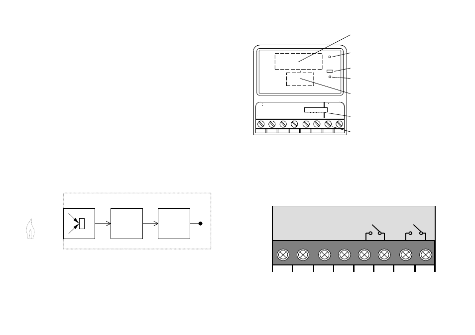
Detector Interior
Fig 4 Detector with Front Cover removed
Electrical Connections
The flame detector has eight connection terminals as show in Fig 5. Removing the front cover of the
flame detector accesses the connections. The cable is passed through the gland holes in the base
of the detector.
Fig 5 Electrical Connection Terminals
Supply ON (Green) - Steady if detector
functioning correctly
IR Optics -
IR optical flame sensors
& filters
Fire (Red) -
Indicates a FIRE detected
Test (Yellow) -
Indicates detector in test
mode
UV Optics (Option) -
UV optical flame sensor
if fitted
DIL Switch -
Select detector functions
1
2
3
4
5
6
7
8
FLAME DETECTOR
TO EN 54-10
6903
4
2
1
1
0
3
SENSITIVITY
HIGH CLASS 1
LOW CLASS 3
5 6 7
8
Connection Terminals
+IN
-IN
Test Input
+R
-R
FLAME
(N/O)
Relay RL1
FAULT
(N/C)
Relay RL2
+24Vdc Supply
Input
1
2
3
4
5
6
7
8
Normally closed
(N/C) when
powered
Closes if flames
detected