Fire Fighting Enterprises FIRERAY 2000 EExd User Manual
Page 9
Page 9 of 12
10
20
40
60
80
100
TRANSMITTER REQUIRES 2 CORE SCREENED WIRING
TO SUITABLE POWER SUPPLY, PLUS ENCLOSURE
EARTH BONDING.
THE ENCLOSURE EARTH BOND MAY BE CONNECTED
TO THE INTERNAL OR EXTERNAL EARTH TERMINALS
AND MUST NOT BE OMITTED.
-VE
+VE
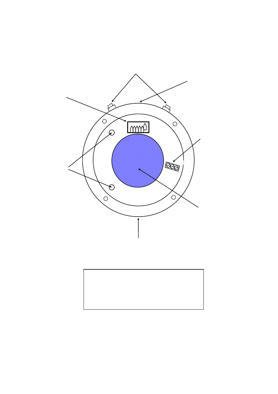
Do not route wiring within the
50mm circular central area, to avoid
obscuring optical components
Internal Earth stud
will be found in one
of these two positions
External Earth terminal will be
found in one of these two positions
User wiring terminals.
Wire only to the -VE and +VE
terminals. (Middle ‘SIG’ terminal
not used on Transmitter units)
Field wiring must be correctly
terminated with insulation stripped
no more than 1mm from connector
terminal.
User wiring to enter here, via suitable
EExd IIB or IIC approved gland.
VIEW INSIDE TRANSMITTER UNIT WITH TOP WINDOW SECTION REMOVED
SHOWING TERMINALS AND SETTINGS ETC
note: some components not shown for clarity
REF:
Range switch shown set to 100m.
Only one switch position to be
ON at a time
Do not use this hole for cable entry
(EExd blanking plug fitted at factory)