Fire Fighting Enterprises FIRERAY 2000 EExd User Manual
Page 12
Page 12 of 12
FIRERAY 2000 EExd - SYSTEM
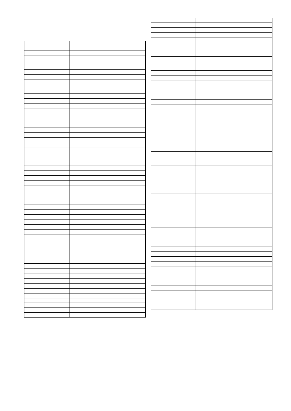
SPECIFICATION
SYSTEM TYPE
Transmitter (TX)
Rugged for EExd IIB areas - IP67
Receiver (RX)
Rugged for EExd IIB areas - IP67
Controller (CU)
Designed to be sited outside the hazardous
area. Rugged for light industrial and
domestic use - IP50
CERTIFICATION
SIRA03ATEX1504
CONFORMS WITH
EExd General
requirements)
BS EN 50014 : 1998
EExd enclosures
BS EN 50018 : 2000
Fire Alarm Systems
BS 5839 : Pt 5 : 1988
Emc Immunity
BS EN 61000-6-2:1999
Emc Emissions
BS EN 61000-6-4:2001
Alarm Systems - EMC
BS EN 50130-4 1996
ATEX Directive
94/9/EC
TEMPERATURE
Range
-20
C to +55
C
THRESHOLDS
Alarm
25%, 35% or 50%**, switch selectable
(1.25db, 1.87db or 3.01db**)
** For full compliance with BS5839 Pt.5,
use 25% and 35% thresholds. 50%
threshold is normally recommended for retro
mode.
Fault
>=93% (11.55db), fixed
DETECTION TIMES
Fire
10 seconds (min)
Fault
5 seconds (min)
SYSTEM RANGE
Minimum
10m
Maximum
100m
TRANSMITTER
Type
Pulsed, Focused Infra-Red beam
Beam Half-Angle
1
approx
Spectrum
Nominally 880Nm (Near Infra-Red)
Max IR O/P (mean)
6.4mW/Sr at IR LED
Max IR O/P (peak)
800mW/Sr at IR LED
Misalignment angle
@25% and (@ 50%) threshold settings
During installation
+/-1
(+/-1
) for a measurable signal
After installation
+/-0.5
(+/-0.75
) (After perfect alignment)
Connections
2 wire, power only required - no connection
to other system parts necessary
RECEIVER
Misalignment angle
@25% and (@ 50%) threshold settings
During installation
+/-4
(+/-5
) for a measurable signal
After installation
+/-3
(+/-4
) (After perfect alignment)
Connections
3 wire, connected to Controller Unit only
SUPPLY VOLTAGES
(At each detector component)
Tx (nominal)
+12Vdc to +24Vdc
Tx (min/max)
+11.5Vdc to +28Vdc
Control/Rx (nominal)
+12Vdc to +24Vdc
Control/Rx (min/max)
+11.5Vdc to +28Vdc
Rx
N/A, Supplied from Control Unit
SUPPLY CURRENT
Control/Rx (Normal)
7.5mA @ all ranges
Control/Rx (Alarm)
13.5mA @ all ranges
Tx
1.6mA @10m to 5.6mA max @100m
SUPPLY RIPPLE
Tx
0.5V p-p min, sine, 50-100Hz @11.5Vdc
Immunity increases with higher supply
voltage
Control/Rx
0.5V p-p min, sine, 50-100Hz @11.5Vdc
Immunity increases with higher supply
voltage
SYSTEM RESET
Internal
Via slider switch in controller unit
External (1)
Remote Reset input - Ground for >5mS
External (2)
Power break for 1 second then re-power
INITIALISATION
TIME
Following reset
50 seconds
SYSTEM OUTPUTS
Fire Alarm
Voltage-Free SPCO contacts, switch
selectable for latching or auto-reset
operation.
Fault Alarm
Voltage-Free SPCO contacts, auto-resetting
operation
Contact ratings
1.0A @ 24Vdc (resistive)
0.3A @ 24Vdc (Inductive)
0.5A @ 120Vac (resistive)
0.2A @ 120Vac(inductive)
Meter Output
DC output proportional to signal strength,
for alignment and maintenance check
purposes
Meter Range
No signal
Low signal
Normal signal
High signal
2.7Vdc to 6Vdc approx
2.7Vdc
>2.7Vdc to <4.1Vdc
4.25Vdc +/-0.15Vdc
> 4.4Vdc
COMPENSATION
(AGC)
Function
Detects and corrects for Rx/Tx lens
contamination, or minor gain errors after
installation or reset.
Update Period
Every 1.5 hours
Correction step
Approx 7% per step
Correction Range
Approx -28% to +77% (% with respect to
initial setting)
SYSTEM CABLING
Max Cable Run
100m to any system part
Cable Type
Screened (MICC recommended)
Max Capacitance
100pF/m
SIZES
Controller
215mm x 265mm x 88mm
Heads
120mm x 125mm x 125mm
Brackets
172mm x 124mm x 56mm
WEIGHTS
Controller
1060 grammes
Tx
2140 grammes
Rx
2165 grammes
Brackets
1530 grammes
FINISH
Controller
White Powder Coat, to RAL 9010
Heads
Red Powder Coat to RAL 2002
Brackets
Red Powder Coat to RAL 2002
Document Number:
23989.00.01