FEC DSP1500 (SAN3) User Manual
Page 6
enFORCE
Operation Manual
PAGE 4 - 6
Chapter 4: System Setup and Wiring
M
OT
O R
A
C 2 00 - 2 2 0 V
P
L C
T
/ D
SAN3-24S
1
:
F
G
2
:
W
3
:
V
4
:
U
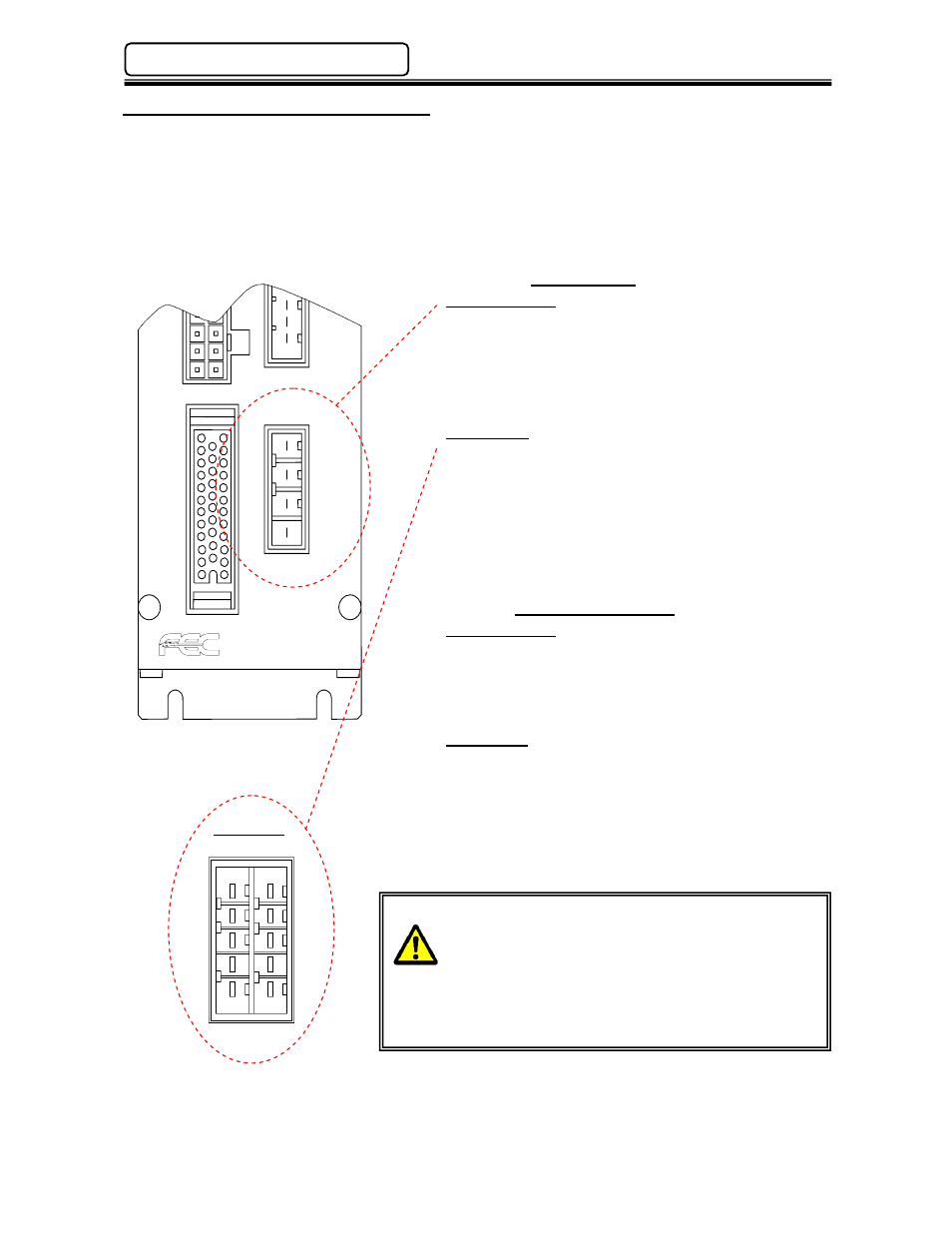
4.4 Input Power Supply Connection
Adequate circuit protection must be provided for the SAN unit input power.
Recommended conductor size should be a minimum of #16AWG.
Suggested color code (FEC standard): U – Red, V – White, W – Black, FG – Green.
Wiring Chart
SAN3-24S, 40S
4:U
3-Phase
3:V
180 ~ 242VAC
2:W
50/60Hz.
1:FG
SAN3-120S (Shown Below)
A5:U
B5:U 3-Phase
A4:V B4:V
180 ~ 242VAC
A3:W B3:W
50/60Hz.
A2:NC B2:NC
A1:FG B1:FG
*Connect wires to both the A side and B side.
Mating Connectors
SAN3-24S, 40S
Manufacture:
AMP
Housing Part No.:
1-178128-4
Contact Part No.:
1-175218-3 (Qty.-4)
SAN3-120S
Manufacture:
AMP
Housing Part No.:
1-917659-5
Contact Part No.:
1-917511-3 (Qty.-8)
Install adiquate circuit protection on the input
power feed. (Refer to Appendix A for wiring)
When using a transformer that is not isolated or if
incoming power is known to be noisy, install a filter
in the input power circuit. Recommended Filters:
SAN3-24S
TDK #ZRWT2205-ME
SAN3-40S
TDK #ZRWT2210-ME
SAN3-120S
TDK #ZRWT2220-ME
SAN3-120
5
4
3
2
1
B A