FEC DSP1500 (SAN3) User Manual
Page 25
enFORCE
Operation Manual
PAGE 4 - 25
Chapter 4: System Setup and Wiring
4.13 Tool Connections
Tools are connected to the SAN controller using three or four cables. The first cable connects to the
Load Cell Force Transducer preamp. Second is a combination Motor / Resolver Cable. The third
cable connects the position proximity switches for home and advanced position indication. A fourth
cable is for an external brake if ordered. Each cable is separated from the Motor / Resolver cable to
reduce the possibility of high voltage noise interference. In multiple press systems, each cable is
labeled with a corresponding press number and should be connected to the corresponding SAN
Controller and Tool.
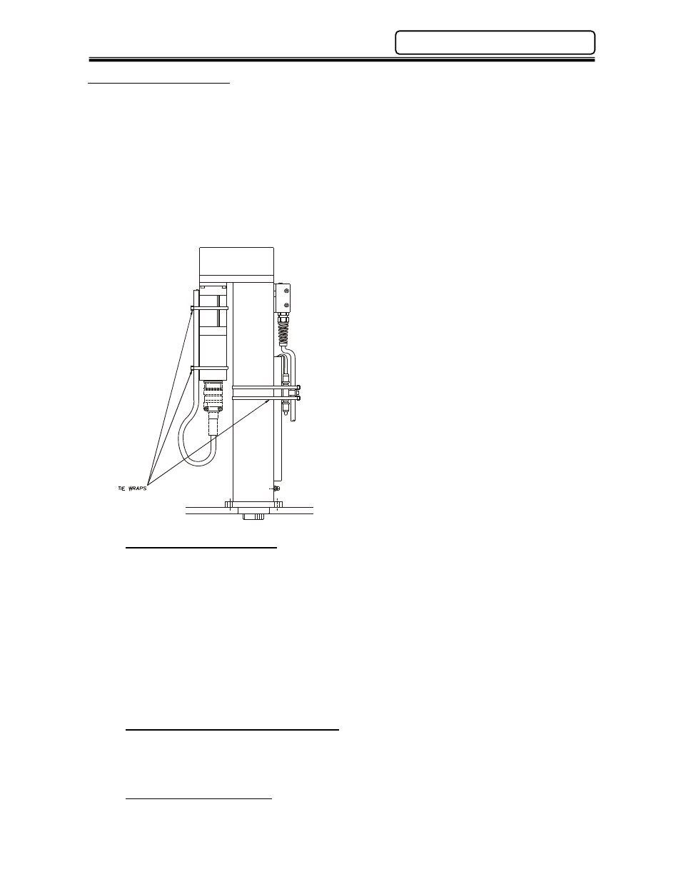
Cables should be secured to the motor similar to the method as shown below. If cable ties are used,
they should be loose enough to allow the cable to move, but yet hold it in place. Cable ties too tight
cause a stress point leading to premature cable failure.
*Recommended Cable Lengths: 75’ or less.
*Maximum
Cable
Lengths:
100’ (must be free
from Electrical Noise)
MOTOR / RESOLVER CABLE
RM1, 2 & 3 MOTOR (FIELD):
FEC
P/N:
FEB-1251
RM4
MOTOR
(FIELD):
FEC
P/N:
FEB-1605
RM1, 2, 3 & 4 MOTOR (EXTENSION):
FEC
P/N:
FEB-1283
Nominal OD = .505”
Min. Bend Radius = 6.0“
RM5 MOTOR (MOTOR FIELD):
FEC P/N: FEB-1604
RM5
MOTOR
(MOTOR
EXTENSION):
FEC
P/N:
FEB-1606
Nominal OD = .415” (x2)
Min. Bend Radius for group = 10.0“
RM5
MOTOR
(RESOLVER
FIELD):
FEC P/N: FEB-1603
RM5
MOTOR
(RESOLVER
EXTENSION):
FEC
P/N:
FEB-1283
Nominal OD = .535”
Min. Bend Radius = 6.0“
LOAD TRANSDUCER (PRE-AMP) CABLE
RM1, 2, 3, 4 & 5 MOTOR (FIELD):
FEC
P/N:
FEB-1173
RM1, 2, 3, 4 & 5 MOTOR (EXTENSION):
FEC
P/N:
FEB-1284
Nominal OD = .405”
Min. Bend Radius = 4.0“
POSITION SENSOR CABLE:
Brad Harrison female 4 pin Micro style cable or equivalent
(See Appendix A)