FEC AFC1150 User Manual
Page 4
)(& ,QF
4.2 Tool
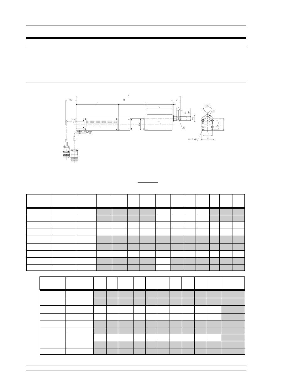
Tool dimensions and mounting specifications are critical in determining the design of the
powerhead that will house the tool assemblies. Caution must be taken to ensure that the tool
assemblies do not come in contact with any other assembly. Torque capabilities of each tool
assembly are specified to aid in determining tool requirements.
4.2.1 Offset Tool
Fig. 4.2.1
Numbers shown in brackets are in inches. All others shown in millimeters as the standard.
202.5
150
30
302M3-O
202.5
220
20
202M3-O
20
34
5.5
10
20
5
202.5
255
40
457.5
497.5
395
13
132M3-O
500
8
801M3-O
500
4
401M2-O
12
24
3.5
5
12
5
140
219
30
359
389
250
4
401M1-O
12
22
3.5
5
12
5
140
195
30
335
365
500
2
201M1-O
3.5
5
12
140
1100
1
101M1-O
3.5
5
12
140
500
1
101M1-O1
K
J
I
H
G
F
E
D
C
B
A
SPEED
(rpm)
TORQUE
(Kg. M)
DRT-
TYPE
19.0 (.748)
302M3-O
15.8 (.622)
202M3-O
125
27.7
19
M6
45
30
22
57.7
60
54
15.8 (.622)
132M3-O
12.7 (.500)
801M3-O
12.7 (.500)
401M2-O
111
17.9
14
M4
30
18
16
37.9
40
38
9.5 (.374)
401M1-O
87
16.9
12
M4
30
20
13
36.9
40
38
9.5 (.374)
201M1-O
9.5 (.374)
101M1-O
9.5 (.374)
101M1-O1
WEIGHT
(Kg)
U
T
S
TAP
R
Q
P
O
N
M
L
DRT-
TYPE
4.2.2 Straight Tool
CHAPTER 4: INSTALLATION AND WIRING
Page 4 - 4