FEC AFC1500 User Manual
Page 56
AFC1500 Multi-2 Unit Hardware Manual (Rev2.1)
PAGE 5 - 56
Chapter 5: Control Interfaces
5.11.1 Component Descriptions
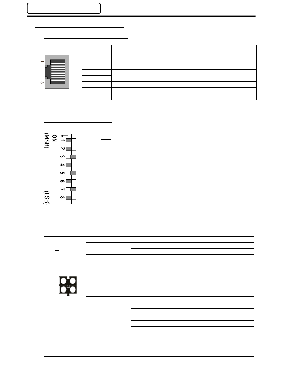
Fieldbus Interface Connections
Pin Signal
Note
1
TD+
2
TD-
3
RD+
4
-
Normally left unused; to ensure signal integrity, these pins are tied
together and terminated to PE via a filter circuit in the module.
5
-
6
RD-
7
-
Normally left unused; to ensure signal integrity, these pins are tied
together and terminated to PE via a filter circuit in the module.
8
-
Configuration DIP Switch
This switch is not used for FEC IP configuration and should be set to all
OFF. The IP address is set-up using the AFC Software (see 5.11.2
below) “Fieldbus Configuration” feature.
Status LEDs
LED
State
Description
1 - Link
Off
No Link Established
On
Link Established
2 - Module Status
Off
Not Powered / Not Online
Green solid
Controlled by scanner in run state
Green flashing
Not configured or scanner in idle state
Red solid
A major unrecoverable fault has been
detected.
Red flashing
A minor recoverable fault has been
detected.
3 - Network Status
Off
No power to device or no IP address
has been set.
Green solid
Online. One or more connections
established.
Green flashing
Data size bigger than configured.
Red solid
Duplicate IP address. Fatal error.
Red flashing
One or more connections timed out.
Green / Red
Self test in progress
4 - Activity
Green
Flashes each time a packet is
transmitted or received.
1
2
3
4