4 interbus s, Interface – FEC AFC1500 User Manual
Page 11
AFC1500 Multi-2 Unit Hardware Manual (Rev2.1)
PAGE 5 - 11
Chapter 5: Control Interfaces
5.4 Interbus S
®
Interface
InterBus S from Phoenix Contact is an open-ring based, distributed device I/O network. I/O data is
transmitted in frames that provide simultaneous and predictable updates to all devices in the network.
This interface board (S - version) has up to 512 bytes of assigned input data and 512 bytes of assigned
output data* (64bytes default). The 64 bytes of assigned I/O data allow a maximum of 512 inputs and
512 outputs per node. FEC I/O is assigned to the I/O points in these data areas (some I/O will be
designated spare). FEC Inputs match the discrete input layout. FEC Output locations are programmed
using the AFC User Console Software.
* When using Master boards where the PCP channel is NOT supported, the maximum number of I/O
will be 20 input bytes and 20 output bytes.
FEC integrates the Interbus S board manufactured by HMS Fieldbus Systems AB into the Multi-2 Unit
modular I/O board. For further technical information on the Interbus S interface go to the HMS website.
(www.hms.se)
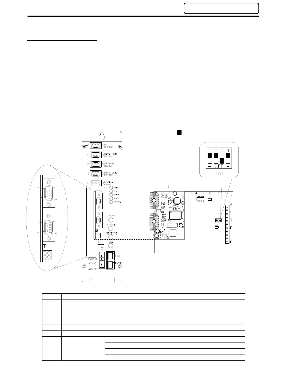
Item
Description
1
Application Connector
2
BUS-IN Connector
3
BUS-OUT Connector
4
Baud Rate Jumper
5
Status LEDs (4)
6
UL LED - Green if voltage is OK at Bus
7
Watchdog LED
Red - (flashing @ 2Hz) - ASIC and FLASH ROM check fault.
Green (flashing @ 2Hz) - module not initialized.
Green (flashing @ 1Hz) - module initialized and running OK.
Red (flashing @ 1Hz) - RAM check fault.
DB9 Connector
DB9 Connector (male)
1
5
6
9
5
1
9
6
RBC
BA
RBDA/ERR
(female)
Daughter board
5
1
5
1
6
9
9
6
2
1
3
4
5
6
7
1
2
3
4
- Represents switch position