FEC AFC1500 User Manual
Page 13
AFC1500 Multi-2 Unit Hardware Manual (Rev2.1)
PAGE 5 - 13
Chapter 5: Control Interfaces
5.4.1 Component Descriptions
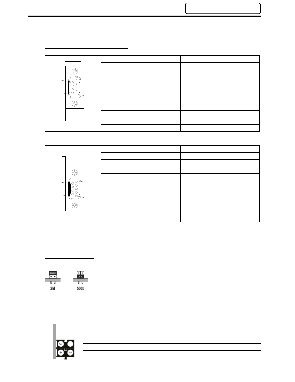
Fieldbus Interface Connectors
Bus IN
Pin No.
Signal
Description
Housing PE
Protective Earth Ground
1
DO1
Data Output
2
DI1
Data Input
3
GND
Signal Ground
4
NC
-
5
NC
-
6
/DO1
Inverted Data Output
7
/DI1
Inverted Data Input
8
NC
-
(9 pin male D-sub)
9
NC
-
Bus OUT
Pin No.
Signal
Description
Housing PE
Protective Earth Ground
1
DO2
Data Output
2
DI2
Data Input
3
GND
Signal Ground
4
NC
-
5
GND
Signal Ground
6
/DO2
Inverted Data Output
7
/DI2
Inverted Data Input
8
NC
-
(9 pin female D-sub)
9
RBST
*
*Always terminate RBST to ground if it is not the last module on the bus. If the RBST is not
connected to ground, the interface will automatically terminate the bus.
Baud Rate Switch
The module supports 2Mbit/s and 500Kbit/s operation. To select the
desired baud rate, just move the jumper cap to the corresponding location.
Baud rate must be selected before power is on and cannot be changed during operation.
Status LEDs
No.
LED
Color
Description
1
CC/RC
Green
Cable connection is good & master not in reset
2
BA
Green
Bus Active
3
RD
Yellow
Remote Bus Disabled
4
TR
Green
PCP - Communication active.
Hold Time = 500ms
5
1
9
6
1
5
6
9