Teledyne LXT-280 User Manual
Page 24
Operation
LXT-280
Teledyne Analytical Instruments
14
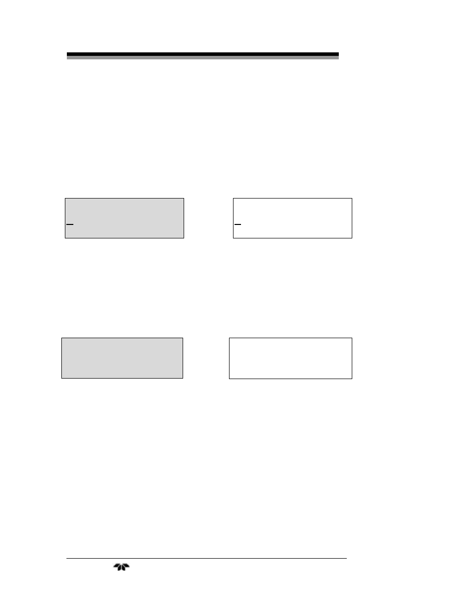
3.2.2 Main Menu
This menu appears after the copyright display when power is first
applied to the LXT-280. The MAIN MENU displays the measured
process variable, temperature, and the current output in percent of full-
scale. While in this menu, the current output can be adjusted and locked
in a manual mode to provide an undisturbed output during sensor
calibrations.
3.2.3 Electrode Data Screen
As an informational screen only, this display provides diagnostic
data pertaining to the electrode. The top line displays the real-time
(active) absolute millivolt value (mVa) the electrode is generating; it is
not compensated for temperature variations.
This value can be used to determine the saturation limit of the
sensor and the maximum effective range of the instrument with that
sensor and electrode. For example, if the maximum desired instrument
range is 20 ppm, and the real-time mVa is 275 mV at an oxygen level of
10 ppm, the maximum effective range of the sensor and electrode is
18.18 ppm. This is calculated by using the equation below. Please note
that the 500 mV value used in the equation is the maximum input to
which the LXT-280 Dissolved Oxygen transmitter will respond.
Effective range = (500 mVa/Input mVa) x (DO value @ the Input mVa)
In the example above, the effective range was calculated as:
DO
90.0 %
50.0%
25.0
O
C
DO
10.0 ppm
50.0%
25.0
O
C
Input
480.0
0 mV
.1
Electrode Diagnostic Screen,DO %
Input
275.0
0 mV
.4
Electrode Diagnostic Screen, DO ppm