Teledyne 402REU - Hydrocarbon analyzer User Manual
Page 36
Chapter 5
Model 402
R-EU
Teledyne Analytical Instruments
5-2
Do not overlook the seemingly obvious. Check to see that power is
available for the instrument (and of the proper voltage, etc.), and that
connections are correct. Also verify that support/calibration gases are not
depleted.
5.1
Measuring Circuit Electrical Checks
If the analyzer performs erratically on zero gas, the trouble can be
related to either the integral gas control systems, or the electronics. To
isolate the problem, the two systems must be separated. To isolate the
electronics, employ the following procedure:
1. Open the door and disconnect the collector cable from the
electrometer-amplifier, leaving it attached to the cell. (Consult
schematic and assembly drawings for circuitry and location,
also see Figure 2-1. ) Do not use a twisting motion—instead,
pull the cable straight up through the hole in the cover. With
this cable disconnected, the electronic circuitry is completely
isolated from the gas control system and cell.
2. Select the lowest measurement range (for maximum sensitivity)
and adjust the zero control until the readout device indicates
above midscale. (The span control should already be set; see
Section 4.8: Stabilization Period.)
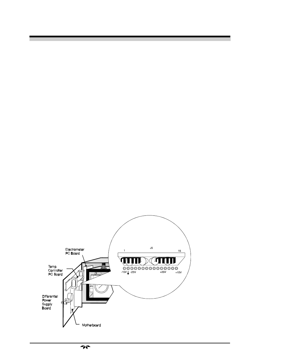
Figure 5-1: Checking the Differential Power Supply