SPP Pumps Auto Prime Hydraulic Submersibles - S4VHL User Manual
Page 8
Manual No/Rev
W79-003E / 4
Operators Instructions for
HYDRAFLOW S4VHL Hydraulic Submersible Pump
Our policy is one of continuous improvement and we reserve the right to alter specifications at any time
Page 8 of 12
remove bearings from shaft. Do NOT use heat
to remove bearing from shaft.
6.4 Pump Assembly:
Assembly is performed in the reverse order
of disassembly with care taken to be sure
that:
6.4.1
After shaft and bearing assembly are installed
in housing, snap-ring (#11) is secured and shaft
rotates freely.
6.4.2
Shaft seal (#25) is kept extremely clean
at all times. Be careful not to scratch
sealing surfaces. Install ceramic seal
seat into rubber boot carefully to be sure
rubber is seated properly. Install seal
cartridge onto shaft carefully using oil to
lubricate the carbon face and the rubber
bellows. Install the impeller slowly to be
sure it contacts the seal evenly and
applies pressure properly to seat the seal
assembly. Be sure carbon face of
rotating cartridge contacts smooth side of
stationary ceramic seat.
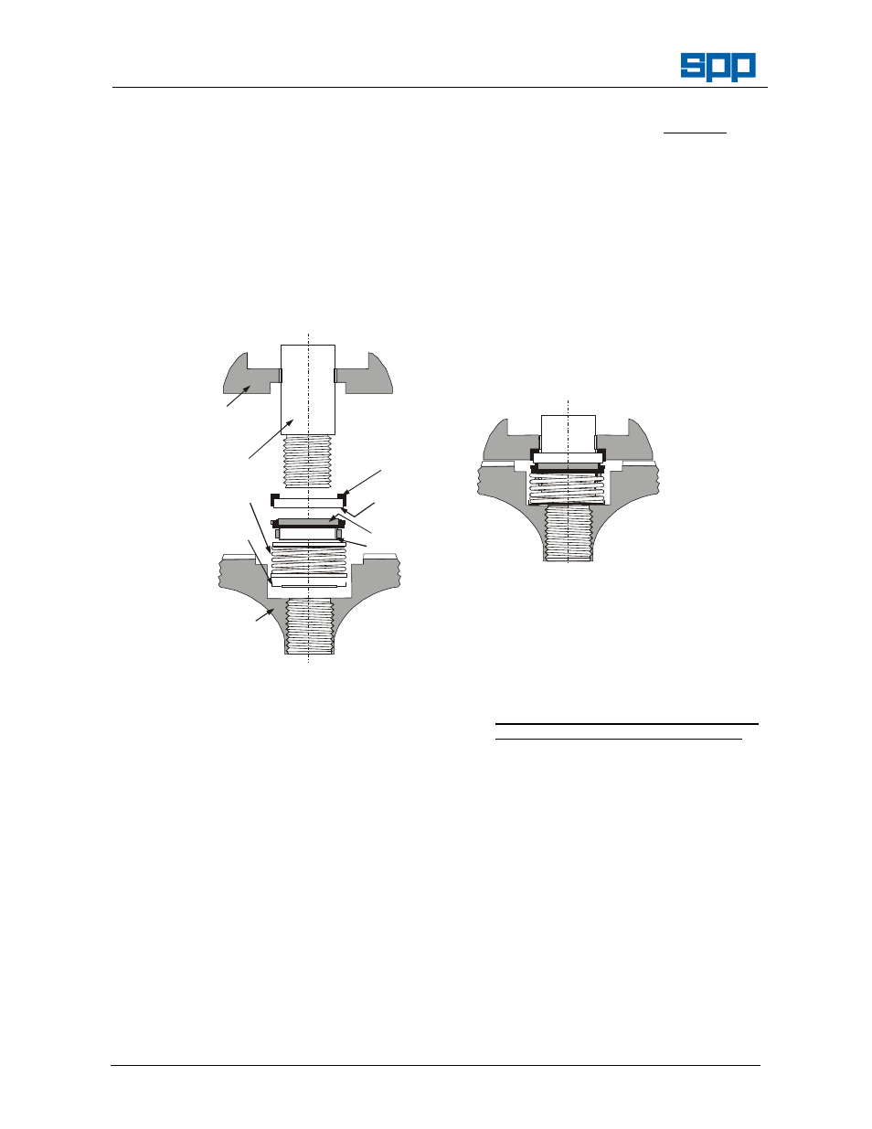
Bearing
Housing
Shaft
Spring
Retainer
Impeller
Rubber Bellows
Carbon Face
Polished
Ceramic Face
Rubber cap
Mechanical Seal Arrangement
Exploded
Mechanical Seal Arrangement
Assembled
6.4.3
"O" ring are properly installed in grooves.
6.4.4
Impeller locking screw (#30) is secured
properly to XX NM torque (40 ft. lbs.)(58
joules).
6.4.5
Drive assembly rotates freely before
installing into volute. The hydraulic motor
and seal will cause some drag. Be sure
hose ports are open on the motor so as not
to get hydraulic binding.
6.4.6
Anti-seize lubricant should be used on all
fasteners when re-assembling pump.
6.4.7
Bearing housing is refilled with oil to the
bottom of the fill plug (#15) spill point.
6.4.8
Before submersing pump, test run on dry
land.
Check for proper rotation of impeller.
(Counter-clockwise looking into volute inlet)
The pump will run backwards and pump
water though at noticeably lower volumes.
6.5 Pump Hose Connection:
NOTE – When the pump hose connections have
been disconnected from the hydraulic motor
it is IMPORTANT to ensure that they are
refitted correctly. Refer to the Figure for the
correct position of each hose connection.