2 introduction, 3 installation – SPP Pumps Split Case Pumps User Manual
Page 5
Pump Installation Guide
Manual No/Rev
W00-002E / 4
Our policy is one of continuous improvement and we reserve the right to alter specifications without giving notice.
Page 5 of 12
2 Introduction
This manual specifies SPP Pumps Limited
requirements for the installation of SPP
horizontal and vertical split case and end
suction pumpsets.
SPP Pumps Limited requires that this
document is given to all contractors with
responsibility for site preparation, electrical
supply and connection, pump installation
and pipework etc.
On completion of all stages that apply, a
signature should be obtained from the
contractor's
representative
confirming
compliance with SPP requirements.
If SPP Pumps Limited Service Department
have been requested to perform initial
testing,
these
documents
MUST
be
submitted signed before commissioning can
be undertaken.
This
guide
covers
the
installation,
connection and initial testing of a SPP
Pumps pumpset, comprising baseplate with
electric
motor,
flexible
coupling
and
centrifugal pump or close coupled pump
unit.
All other items required for the installation
must be provided by the customer or the
contractors responsible for the installation.
2.1
Review of Equipment Received
On receipt of the pumpset it is important to
check for any damage or loss that may
have occurred in transit. Any damage or
missing items should be referred in the first
instance
to
the
haulage
contractor
responsible.
3 Installation
3.1
Pump Location
The pump should be installed as near to the
liquid source as possible, with the shortest
and most direct suction pipe practical.
Allow sufficient access for inspection and
maintenance with enough headroom for an
overhead crane or hoist of sufficient
capacity to lift the heaviest item of
equipment.
Adequate ventilation is required for cooling
purposes, inlet and outlet apertures,
suitably sized and positioned to prevent air
re-circulation, must be provided in the pump
house structure.
3.2
Foundations
A foundation plinth should be constructed to
support each pumpset on a floor area free
from expansion joints. These foundation
plinths should be sufficiently substantial to
absorb vibrations and rigid enough to avoid
any twisting or misalignment.
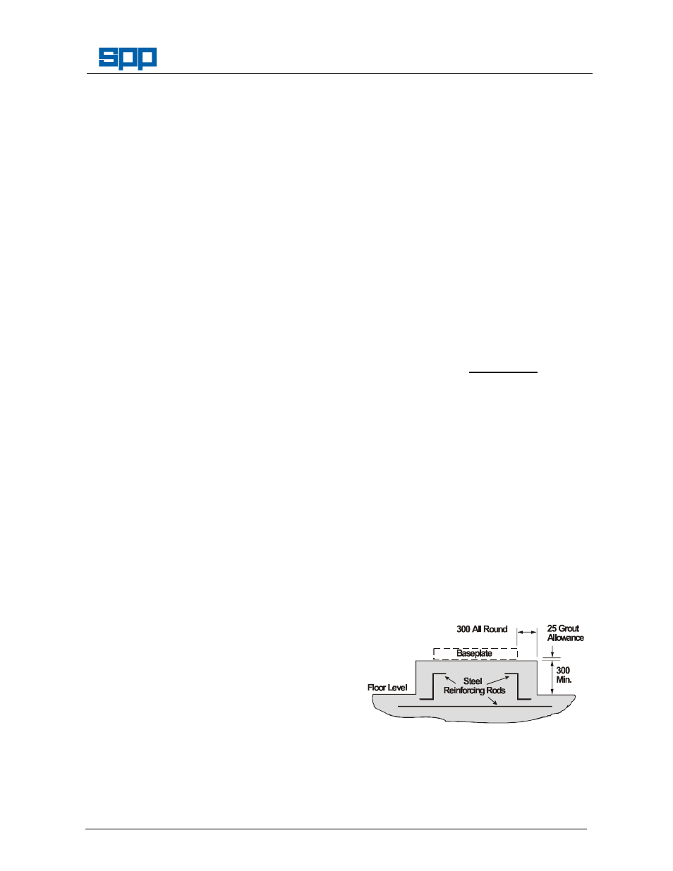
As a rough guide, they should be at least
300mm wider than the pumpset on all sides
and weigh between 1 and 1.5 times the
weight of the pumpset. Plinths for pumps
are recommended to have a minimum
height of 300mm but height should be
sufficient to achieve the necessary weight
and to accommodate the pockets for fixing
bolts.
Foundation height may be calculated thus:
Height (m) =
W
2400 x B x L
where:
W (kg)
= total weight of pumpset
2400 (kg/m
3
) = concrete density
B (m)
= foundation width
L (m)
= foundation length
Use a suitable concrete mixture by volume
is 1:2:3 (Cement : Sand : Aggregate) with a
maximum 100mm slump, and a 28 day
compressive strength of 27,000 N/mm
2
.
Foundation concrete should be poured
without interruption to within 25mm of the
finished height.
The foundation should be reinforced with
layers of 150mm square No.8 gauge steel
wire fabric, or equivalent, horizontally
placed 150mm apart.
The top surface should be well scored and
grooved before the concrete sets to provide
a bonding surface for the grout. The
foundation should be allowed to cure for
several days before installation of the
baseplate.