Tools needed for calibration procedure, Calibration procedure – Server BS/BSA (05020) THERMOSTAT User Manual
Page 3
3
INsTAll INNer Vessel IN sHroUd. reassemble
unit, reversing disassembly procedures above.
If unit previously included a small rubber grommet
on thermostat shaft hole, remove and discard it.
4
INsTAll NeW THermosTAT KNoB BY AlIGNING
KNoB GrooVe WITH sPlINe oN NeW
THermosTAT sHAfT, THeN PUsH KNoB oNTo
sHAfT. (Tighten knob setscrew if used.)
5
seT UNIT UPrIGHT oNTo ITs feeT ANd PlUG
UNIT INTo PoWer soUrCe.
6
CAlIBrATe UNIT Per CAlIBrATIoN
INsTrUCTIoNs.
Factory-installed thermostats are sealed
after calibration.
do not attempt to calibrate a factory-installed
thermostat.
TOOLS nEEdEd FOR
cALIBRATIOn PROcEdURE
• Hexagonal Wrench or Allen Wrench (1.5 mm)
-included in thermostat kit
• dial Thermometer (stem type)
-to measure water temperature from
90
°
to 170
°
f (32.2
°
-76.7
°
C)
• Cover (with hole in it)
-to contain heat within unit and to hold
the dial Thermometer.
cALIBRATIOn PROcEdURE
1
AlIGN KNoB oNTo THermosTAT sHAfT ANd
Press KNoB oNTo sHAfT.
2
TUrN KNoB To seTTING of:
135
°
F (57.2
°
c)
3
CArefUllY remoVe KNoB WITH sTrAIGHT PUll
To AVoId TUrNING THermosTAT sHAfT.
4
PlACe CoVer (WITH Hole IN IT) oVer UNIT
ANd INserT THermomeTer THroUGH CoVer
oPeNING.
5
TUrN UNIT oN ANd AlloW UNIT To HeAT UP To
A mINImUm of: 145
°
F (62.8
°
c)
• The above “Heat Up-To” temperature is
considered a minimum temperature because
exceeding the temperature will not affect the
final calibration.
6
If THe TemPerATUre does NoT reACH THe
mINImUm “HeAT UP To” TemPerATUre,
Hold THe THermosTAT sHAfT WITH oNe HANd
ANd roTATe THe CAlIBrATIoN sCreW 1/2 TUrN
CoUNTerCloCKWIse, UsING THe sUPPlIed
WreNCH. Continue to repeat the 1/2 turn of the
calibration screw, until the temperature reaches
the minimum.
7
WHeN THe TemPerATUre reACHes THe
mINImUm “HeAT UP To” TemPerATUre,
TUrN CAlIBrATIoN sCreW TWo fUll TUrNs
CloCKWIse.
8
AlloW APPlIANCe To Cool To:
135°F (57.2°c)
• If unit does not cool to the above “Cool To”
temperature, turn calibration screw two
additional full turns clockwise.
9
WHeN THe TemPerATUre reACHes THe
“Cool To” TemPerATUre, TUrN CAlIBrATIoN
sCreW CoUNTerCloCKWIse UNTIl A sofT
AUdIBle ClICK Is HeArd (oN). The unit will now
start and continue to heat up until another audible
click is heard (off), this second click indicates that
the heating has stopped.
J
rePeAT sTePs 6 THroUGH 10 UNTIl THe
AUdIBle ClICK Is CoNsIsTeNTlY HeArd WHeN
THe KNoB Is TUrNING BeTWeeN:
142°F (61.1°c) and 152°F (66.74°c)
K
seCUre THe CAlIBrATIoN sCreW BY PlACING
sUITABle THreAd-loCKING mATerIAl, sUCH As
loCTITe, IN THe sHAfT CeNTer.
L
AlIGN KNoB oNTo THermosTAT sHAfT ANd
Press KNoB oNTo sHAfT. If unit includes a knob
guard, install knob guard.
M
re-CHeCK seTTING ANd reTUrN UNIT To
serVICe.
Clockwise rotation of the calibration screw lowers
operating temperature.
Counterclockwise rotation of the screw raises the
operating temperature. rotation of the knob or
the thermostat shaft does just the opposite.
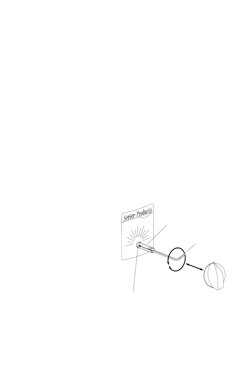
Thermostat shaft
Knob
Removed
Wrench
Turn calibration screw, using wrench,
CoUNTerCloCKWIse for steps 7 and 10.
Turn calibration screw, using wrench,
CloCKWIse for steps 8 and 9.