Old thermostat removal, New thermostat installation – Server BS/BSA (05020) THERMOSTAT User Manual
Page 2
OLd THERmOSTAT
REmOvAL
1
TUrN UNIT off ANd UNPlUG Cord. Allow unit to
fully cool before proceeding to next step.
2
remoVe PlAsTIC dome, PUmP, ANd sTAINless
sTeel BoWl from UNIT.
3
remoVe THe TWo sCreWs AT ToP of
oPerATor’s PANel.
4
remoVe PICTUre AssemBlY.
• For units Series 79 or earlier: remove the
two screws at bottom of picture side and then
slide picture down and out.
• For units Series 80 or later: Turn the two
black plastic 1/4 turn fasteners at bottom of
picture, 1/4 turn counterclockwise, then pull
picture down and out.
5
remoVe THe TWo sCreWs AT ToP of eXPosed
lIGHT PANel.
6
TIP eNTIre UNIT oNTo rIGHT or lefT sIde.
Grasp mask and tilt it toward operator’s side of unit.
7
remoVe rUBBer feeT ANd ANY sCreWs
seCUrING BAse To UNIT. Also remove heyco from
cord to allow base to come loose.
8
remoVe BAse from UNIT.
9
remoVe ANd dIsCArd THermosTAT KNoB.
(Pointer type knobs have a setscrew.)
J
remoVe INsUlATIoN from AroUNd INNer
Vessel.
K
slIde INNer Vessel ToWArds PICTUre sIde of
UNIT UNTIl THermosTAT sHAfT CleArs froNT
PANel.
L
CUT WIre TIe, If THere Is oNe, To fUrTHer
ACCess WIrING ANd THermosTAT.
M
dIsCoNNeCT BoTH leAds To THermosTAT.
N
remoVe INNer Vessel from UNIT.
O
remoVe HArdWAre seCUrING THermosTAT
To THermosTAT BrACKeT ANd dIsCArd
defeCTIVe/old THermosTAT. You may need to
save the old mounting hardware for installing new
thermostat.
nEw THERmOSTAT
InSTALLATIOn
1
INsTAll NeW THermosTAT oNTo THermosTAT
BrACKeT WITH INNer Vessel IN AN
UPsIde-doWN PosITIoN. Align thermostat with
angled terminal pointing upward.
secure thermostat with mounting hardware.
2
THermosTAT CoNNeCTIoNs
• For units Series 79 and earlier:
Thermal cut-out in kit will not need to be used.
Cut off round/ring terminal from lead which is still
connected to indicator light.
Then strip this end of lead by removing about 1/2”
of insulation which it is wrapped in.
Connect 3” non-insulated lead (supplied in kit) with
wire nut (also supplied in kit) to stripped lead which
is still connected to indicator light.
Connect female terminal end of 3” non-insulated
lead to thermostat terminal which points straight
out from thermostat.
Cut off round/ring terminal from other lead which
was previously disconnected from thermostat.
Then strip this end of lead by removing about 1/2”
of insulation which it is wrapped in.
Connect other 3” insulated lead (also supplied in
kit) with other wire nut (also supplied in kit) to this
other lead which was previously disconnected from
thermostat.
Connect female terminal end of 3” insulated lead to
thermostat terminal which points at an angle out
from thermostat.
Be certain that the insulation on the 3” lead is
covering the terminal connection to the thermostat.
• For units Series 80 and later:
3” insulated lead and one wire nut in kit will not
need to be used.
Cut off 3”, nearest to thermostat, of the lead that
connected the heating element to the thermostat.
Then strip this end of lead by removing about 1/2”
of insulation which it is wrapped in.
Connect the 3” non-insulated lead (supplied in
kit) with wire nut (also supplied in kit) to stripped
lead which connected the heating element to the
thermostat.
Connect female terminal end of 3” non-insulated
lead to thermostat terminal which points straight
out from thermostat.
remove and discard other lead which was
disconnected from thermostat and replace with new
thermal cut-out (supplied in kit).
Connect female terminal end of thermal cut-out
lead to thermostat terminal which points at an
angle out from thermostat.
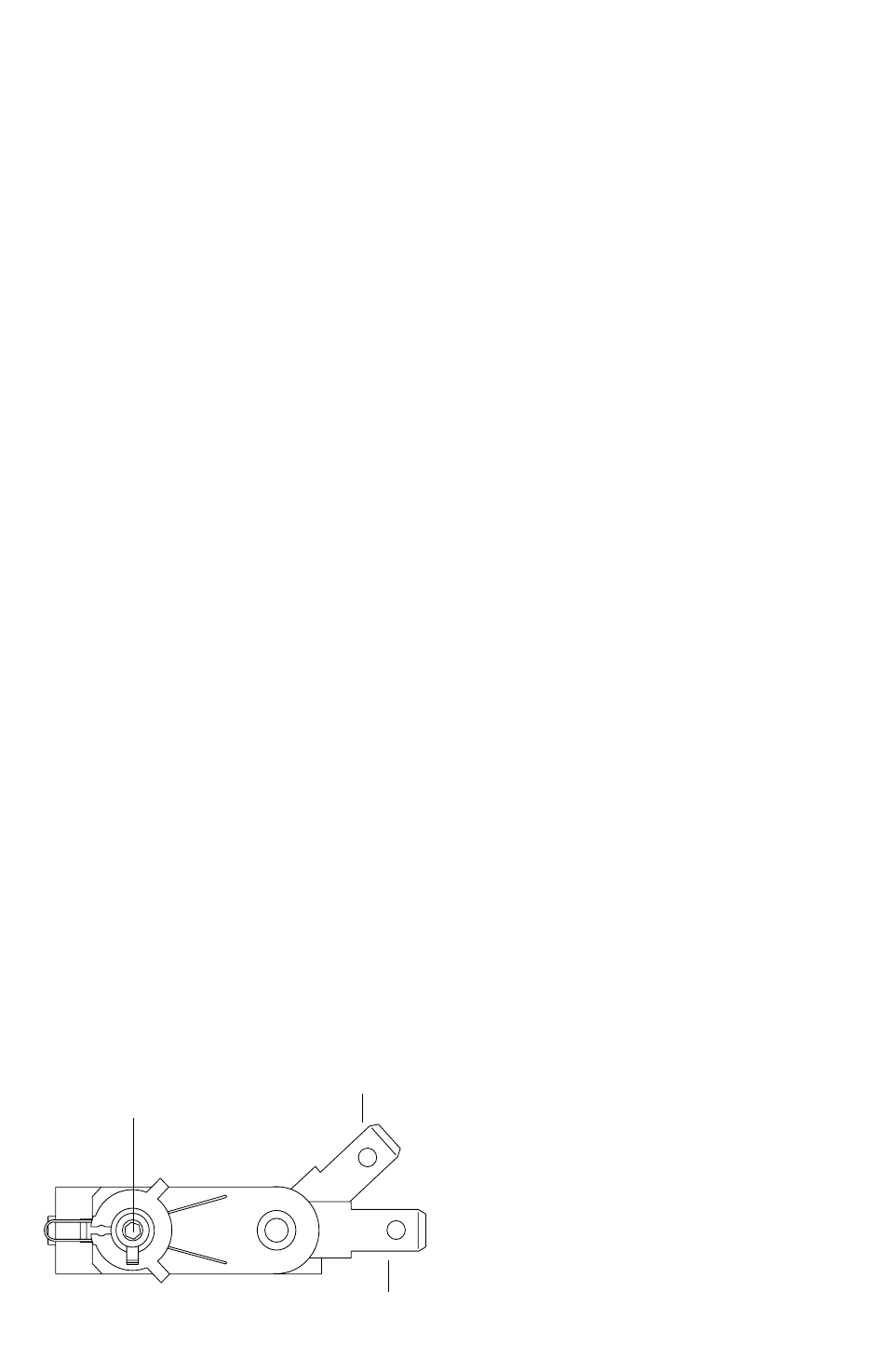
Thermostat shaft
straight Terminal
on Thermostat
Angled Terminal
on Thermostat