Hardware setup, Asus p4t-e user’s manual 39, Connectors 3. h/w setup – Asus P4T-E User Manual
Page 39
ASUS P4T-E User’s Manual
39
3. HARDWARE SETUP
Connectors
3. H/W SETUP
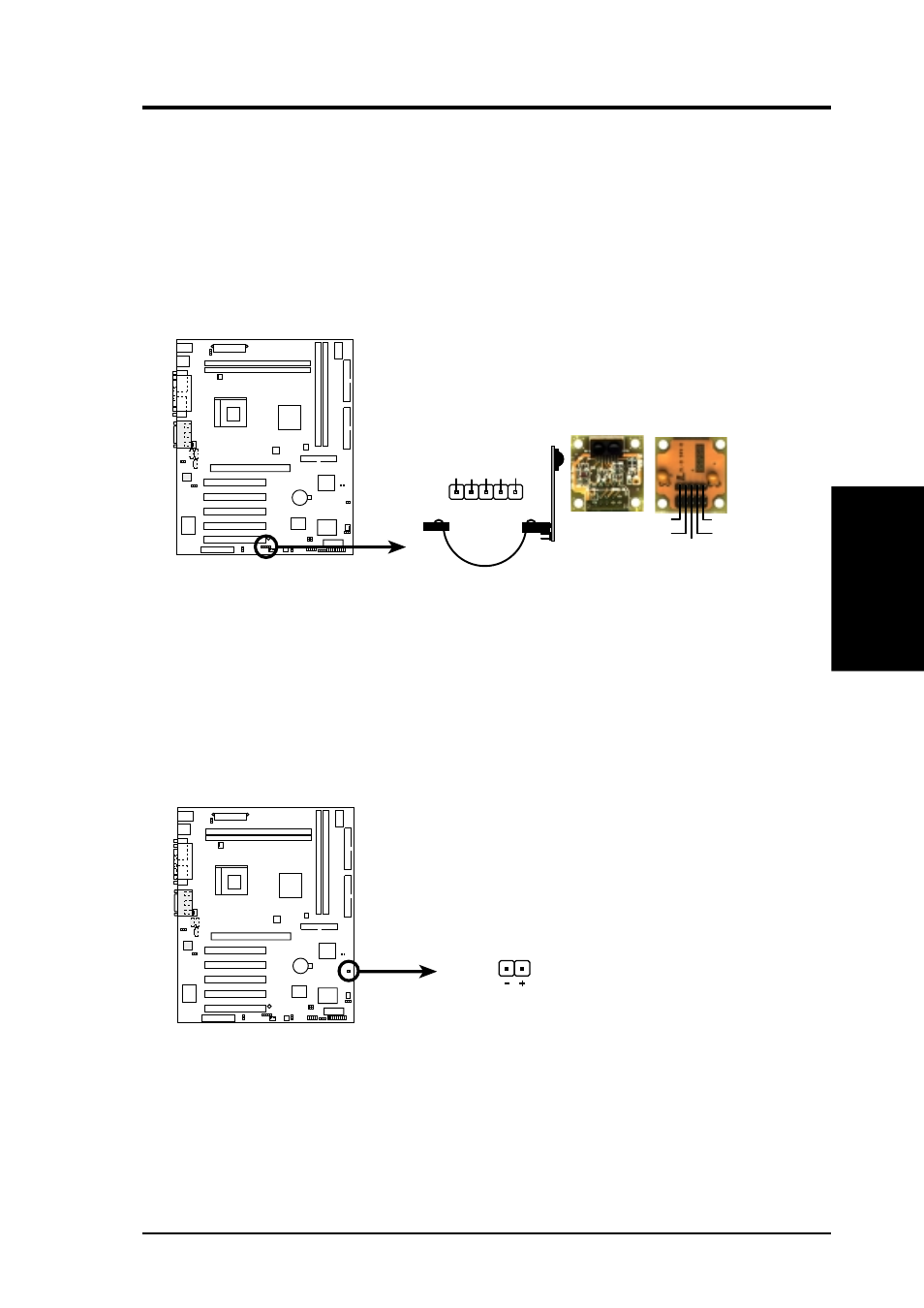
P4T-E
P4T-E Infrared Module Connector
Front View
Back View
+5V
IRTX
IRRX
(NC)
GND
+5V
IRRX
IR
TX
(NC)
GND
IR
1
16) Standard and Consumer Infrared (SIR) Module Connector (5-pin IR)
This connector supports an optional wireless transmitting and receiving infrared
module. This module mounts to a small opening on system cases that support
this feature. You must also configure the setting through UART2 Use Infrared
(see 4.4.2 I/O Device Configuration) to select whether UART2 is directed for
use with COM2 or IrDA. Use the five pins as shown in Back View and connect
a ribbon cable from the module to the motherboard’s SIR connector according
to the pin definitions.
P4T-E
P4T-E HDD Activity LED
TIP: If the case-mounted LED does not
light, try reversing the 2-pin plug.
HDDLED
17) IDE Activity LED (2-pin HDLED)
This connector supplies power to the cabinet’s IDE activity LED. Read and
write activity by devices connected to the Primary/Secondary IDE and Primary/
Secondary ATA100 connectors will cause the LED to light up.