4 network setting – Approach Tech DVR-3704T User Manual
Page 27
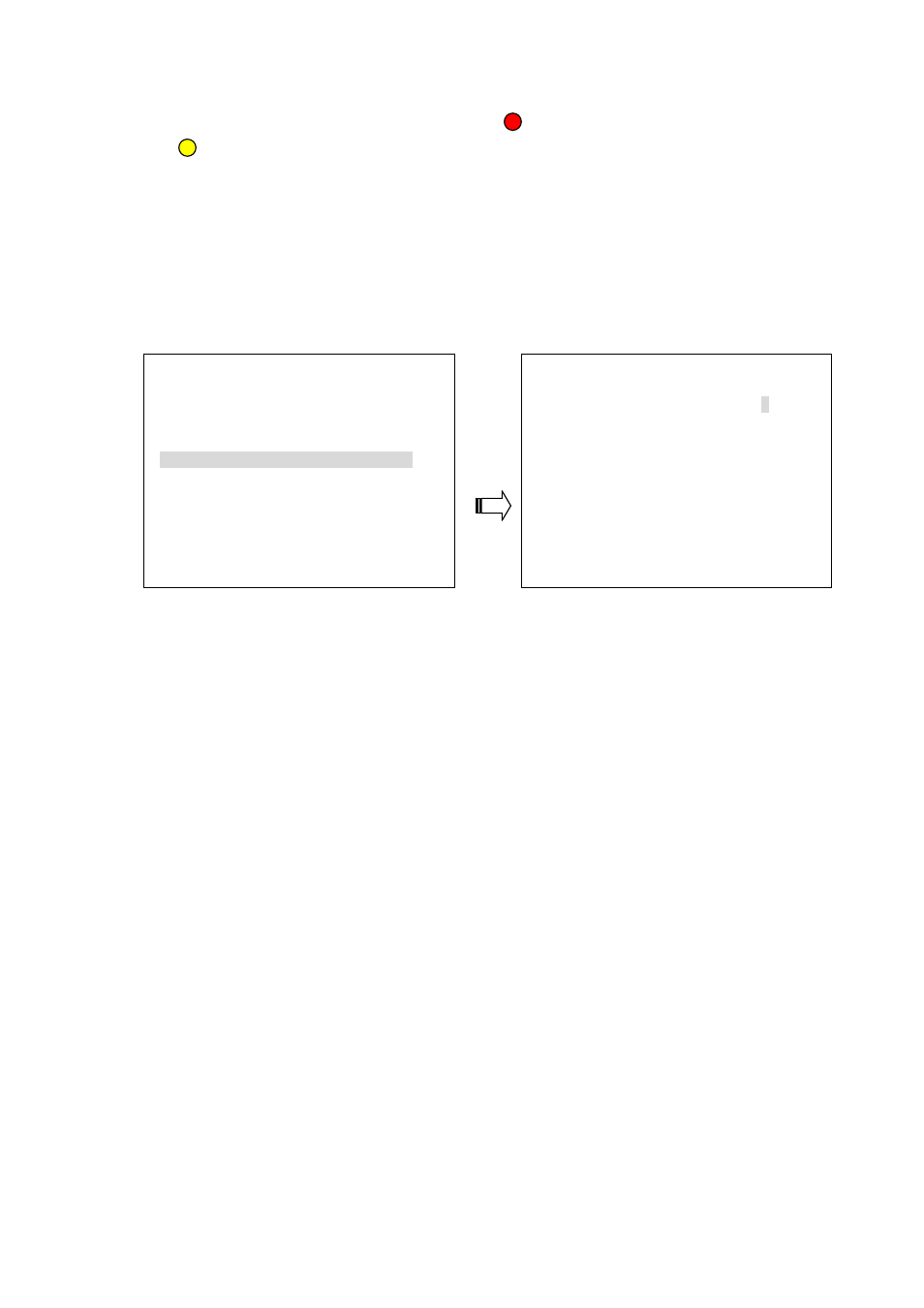
The user needs to see the situation in each channel in order to set a detection zone within the 8W
×
6H (48) area. The effective points are marked “ ” (red) and the ineffective points are marked
“ ” (yellow).
The user can use the manual mode to set the target area. Please press the “^”, “v”, “<” or “>”
buttons to select the points, and use the Enter button to mark them one by one; or press the
Save button to activate the whole points.
5.5.4 NETWORK SETTING
ADVANCED SETTING
NETWORK SETTING
1.RECORD SETTING
ENTER
1.NETWORK PASSWORD
9999
2.ALARM SETTING
ENTER
2.PORT DATA/CMD
5000/5001
3.MOTION SETTING
ENTER
3.IP ADDRESS
192.168.001.224
4.SUBNET MASK
255.255.254.000
4.NETWORK SETTING
ENTER
5.GATEWAY 192.168.001.254
5.SCHEDULE SETTING
ENTER
1. NETWORK PASSWORD:
The default admin password is 9999.
2. PORT DATA/CMD: The option is to set the transfer ports of the image data and command data.
Note: The values of DATA/CMD ports must be the same with the setting of the Network Viewer
software (refer to chapter 7).
3. IP ADDRESS: The IP
address may be manually edited.
4. SUBNET MASK: The IP mask may be manually edited.
5. GATEWAY: The gateway may be manually edited.
NOTE: When only one unit of the DVR is connected to a computer or LAN, you can freely
assign an IP address for the DVR. For example, there is a range of DVR IP addresses from
192.168.1.1 to 192.168.1.255. You can pick one for use from the range of the IPs. It’s not
necessary to set MASK and GATEWAY; leave the settings as default.
When a DVR is connected to a WAN, you must acquire a unique, permanent IP address
and correctly configure the MASK and GATEWAY settings according to your network
architecture. If you have any questions regarding these settings, please contact a qualified
MIS professional or your ISP.
25