Battery cable connection, Ac cable size – PROLiNK IPS3000 User Manual
Page 8
6
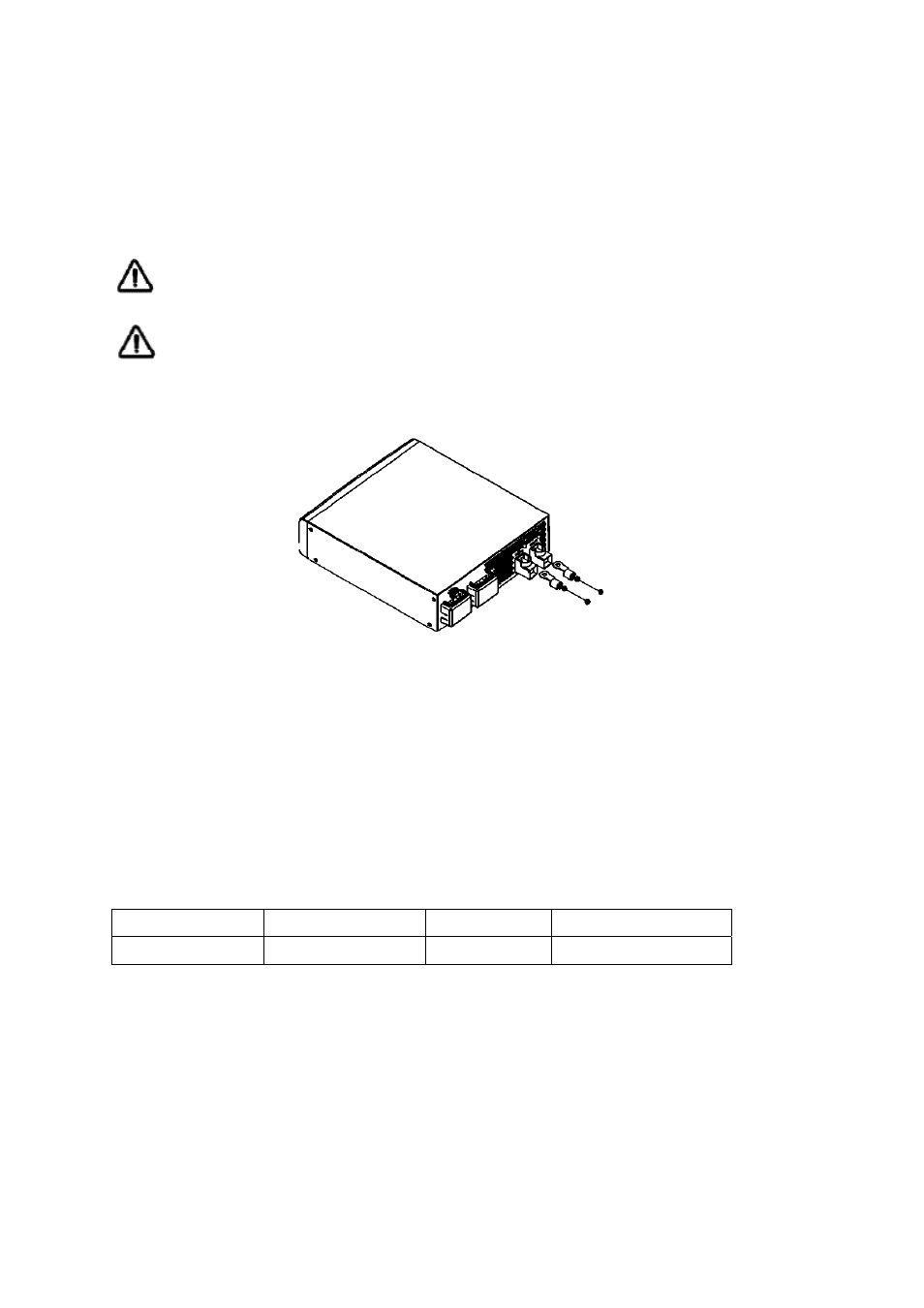
Battery Cable Connection
Observe Battery Polarity! Place the ring terminal of DC cable over the bolt and directly against the unit’s
battery terminal. Tighten the M6 screw with 5-8 Nm. Do not place anything between the flat part of the
Backup System terminal and the battery cable ring terminal or overheating may occur.
DO NOT APPLY ANY TYPE OF ANTI-OXIDANT PASTE TO TERMINALS UNTIL AFTER THE
BATTERY CABLE WIRING IS TORQUED!!
Figure 5 illustrates the proper method to connect the battery cables to the unit terminals.
WARNING: Shock Hazard
Installation must be performed with care for the high battery voltage in series.
Caution!! Do NOT place anything between battery cable ring terminals and terminals on the
inverter. The terminal screw is not designed to carry current.
Apply Anti-oxidant paste to terminals AFTER terminals have been screwed.
Verify that cable lugs are flush with the battery terminals. Tighten battery cables to terminals (5-8 Nm).
Figure 4 Battery Cable Connect to unit
AC Cable Size
Before wiring the input and output of inverter, refer to table 2 for minimum recommended cable size and
torque value
Table 2 Recommended cable size and torque value for AC wire
Model Number
AC Input
AC Output
Torque value
IPS3000P 12AWG
12
AWG
1.2~1.8
Nm