Introduction, Component identification, Theory – Poweramp AP SERIES AIR POWERED 4.2009 User Manual
Page 9
7
4111-0009 — Oct 2007
Jan 2009
INTRODUCTION
Component Identification
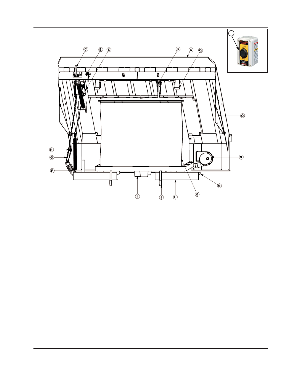
A — Lip
B — Lip Assist Rod
C —Lip Linkage Assembly
D — Lip Latch Assembly
E — Lip Maintenance Prop Pivot)
F — Lip Actuator Chain Spring
G — Lip Actuator Chain
H — Lip Actuator Chain Adjustment Link
I — air bag support pallet
J — Lip Keepers (2 used)
K — air bag
L — Main Frame
M — Maintenance Prop
N —Blower Motor
O —Toe Guard (2 used)
P —Raise Button
Q —Safety Legs
The AP dock leveler uses a blower motor and
one-button operation for ease of use.
The dock leveler can be operated remotely using the
RAISE button (P) on the control panel . This
activates an electric blower motor (N). The blower
forces air into the air bag (K), causing the platform to
rise. Releasing the RAISE button allows the platform
to lower.
When the platform rises to the point where there is
2 — 3 in. (51 — 76. mm) from its full raised height, the
lip spring (F) and lip actuator chain (G), causes the
lip linkage assembly to push the lip out and up. The
lip assist spring (not shown) also helps keep the lip
extended. When the lip is fully extended, the lip latch
cable engages the lip latch assembly, locking the lip
in the extended position. The dock leveler has
reached its full height when the lip is fully extended.
To lower the platform, release the Raise button (P).
The platform will lower until the extended lip rests on
the truck bed. If the lip did not fully extend or there is
no truck at the dock the platform will lower until one
of the following conditions occur:
-- Lip is resting on lip keepers (cross-traffic position).
-- Leveler went to the below-dock position, lip folds
automatically, leveler rests on the safety legs
(below dock position).
-- Leveler went to the below dock position with
operator holding the safety leg retract cable
(not shown), safety legs are retracted, lip folds
automatically causing dock to rest in the full below
dock position.
THEORY
P