Adjustments, Valve adjustment procedure hoke / kti – Poweramp EH SERIES HYDRAULIC User Manual
Page 29
27
4111-0004 —November 2003
Rev “B” February 2011
ADJUSTMENTS
S1 Sequence Valve 1
Controls the Platform Cylinder. When the leveler has
reached the top of its travel allow the leveler to float
down. Fluid should flow through the NV1 valve. If you
hear the motor spinning backwards, or Leveler and/or
Lip may dropping prematurely adjust S1 clockwise in
small increments, testing each time, until the motor is
not spinning backwards or Leveler and/or Lip may drop
correctly.
S2 Sequence Valve 2
Controls the Lip Cylinder. This valve should be set to
allow a smooth, quiet shift. Turning S2 counter-
clockwise causes the lip to extend.
If the lip does not extend turn S2 counter-clockwise out
small increments until lip begins to extend. Once the lip
is extended allow the powerpack to operate in pressure
relief, then allow the leveler to return below dock.
Raise the leveler and continue to adjust the S2 valve to
allow a smooth, quiet shift. When adjusted properly, the
lip should stay extended until below dock. Lip
extension cycle should not take more than a few
seconds.
NV1 Need Valve 1
Controls the Down speed of the ramp cylinder.
Increase Down speed by turning NV1 counter-
clockwise,
Decrease Down speed by turning NV1 clockwise.
RV2 Relief Valve 2
Allows the lip to collapse below dock, protects the lip if
it is backed in to. Set the RV2 valve by backing out
adjustment screw as far as it goes.
Return leveler to keepers and begin to raise it.
Halfway up, allow the leveler to return for a second,
then raise leveler. The lip should not extend. If lip
extends, turn S2 valve clockwise 1/4 turn and repeat
until lip does not extend.
PO CHK Pilot Operated Check Valve
Keeps Lip from collapsing until it is below dock. This
valve is not adjustable. If lip malfunctions, cleaning or
replacement may be required.
RV1 Main Relief Valve
Sets system pressure
2W 2 Way Normally Open Spool Valve - Optional
If present, can extend lip with Lip Out option or it can
be used as an emergency stop if power is not running.
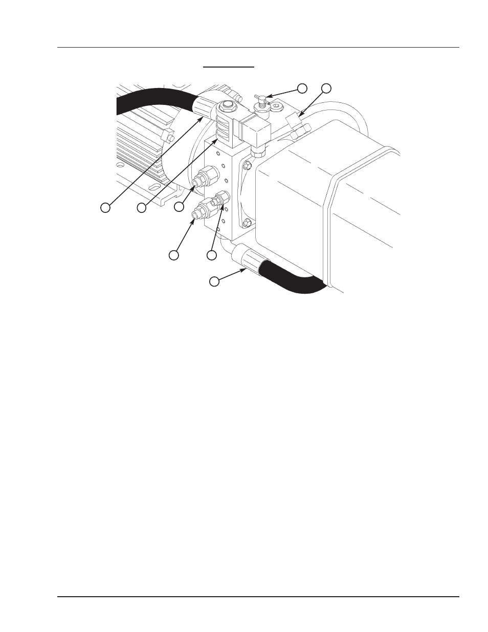
A—S2 Valve
B— RV1 Valve
C—S1 Valve
D— 2W NO Spool Valve/Coil
E— NV1 Valve
F— Breather Tube/Fitting
G—To Hoist Cylinder
H—To Lip Cylinder
*Note: Not pictured on the bottom of the valve body are the RV2 and PO Check Valves
Valve Adjustment Procedure Hoke / KTI
B
A
D
F
E
G
H
C