Nova-Tech LMI Roytronic Series A Metering Pump User Manual
Page 21
21
OPERATION
4.4
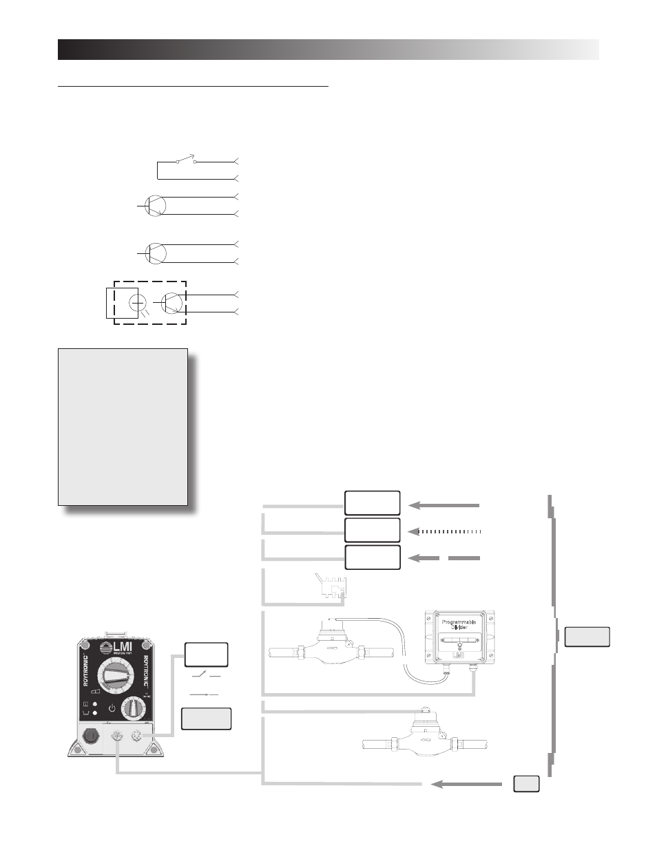
Methods of Externally Triggering or Pacing A3, A7, and A8 Pumps
Switch or transistors must be capable of switching 24V DC at
15 milliamperes. Minimum time in low impedance state (ON) is
25 milliseconds. Minimum time in high impedance state (OFF)
is 50 milliseconds.
NOTE: Pins 1 (Brown wire) and 2 (White wire) must be connected/
shorted together in order for the pump to be ‘ON’ in external
mode.
4. Opto
Isolator
2. NPN Transistor
Base goes high
to trigger pump
White
3. PNP Transistor
Base goes low
to trigger pump
Method of Triggering A3, and A7 Pumps Through External Control Connector
1. Switch Closure
Switch closing
triggers pump
PIN
3
2
3
2
3
2
3
2
Blue
− White
+ Blue
− White
+ Blue
− White
+ Blue
Full (Open)
Empty (Closed)
4-20 milliamp DC
4-20 milliamp DC
Higher Frequency Pulses
Lower Frequency Pulses
Pulse
Transmitter
MICROPACE
™
4 DIGIT DIVIDER
MP-400D
MICROPACE
™
A/D CONVERTER
MP-100
MICROPACE
™
4 DIGIT MULTIPLIER
MP-500M
RFP Flowmeter
Programmable
Divider
Programmable
Divider
FC Flowmeter/Contactor
A3, A7, A8
A3, A7
A8
Optional
Low Level
Sensor
The default configuration
for the Remote On/Off
input is: open contacts
= pump stopped, closed
contacts = pump enabled.
Therefore pins 1 and 2
of the External Control
Connector must be shorted
together in external mode
for the pump to respond to
external signals.
These pumps have two operating modes: Local (Pulse Indicator Light flashes
green) and Remote (Pulse Indicator Light flashes yellow). Pressing the Power/
Mode Selection Button switches between Local and Remote modes. The default
configuration for operating mode is Local mode.
When the pump is in Local mode the Remote On/Off input is ignored. When the
pump is in Remote mode the Remote On/Off input is always monitored. The
pump will return to the last power mode if power is interrupted.