Appendix 3, Electrical drawing, General – Nova-Tech B4000-M User Manual
Page 4
1 8
1
Instructions manual
Instructions manual
APPENDIX 3
TP2: Inner temperature sensor of chamber
TP3: Temperature sensor of chamber wall
V1: Air/Steam release valve
V2: Water release valve
ELECTRICAL DRAWING
The sterilizer described in this manual is intended for the sterilization
of research tools. It operates automatically with 134°C and 121°C
sterilization temperatures. This sterilizer is in compliance with the
European Directive 93/42/CEE and it has been produced in accordance
with the EN 13060. In addition the chamber has been ASME certified.
For safe operation, please pay close attention to the alert symbols
below which cab be found throughout this manual. Please
carefully read and understand the contents of this manual prior to
operating this instrument.
HOT SURFACE.
This symbol represents a hot surface
This symbol is used to draw the attention of the reader to
particularly important notions for operator safety.
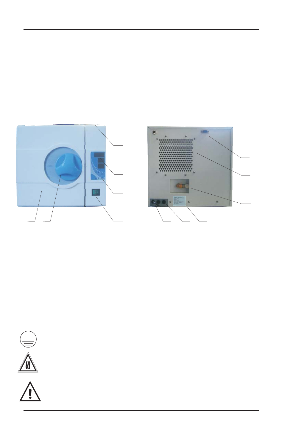
1 Distilled (Clean) water tank
2 Display
3 Control panel
5
6
4 Power switch
Door handle
Door
7
8
Back Panel
Condenser ventilation
9 Safety valve
10 Serial/Electrical Label
11 Fuses
12 Power cord
1. General
5
4
3
2
1
6
7
9
8
12 11 10
T12A
T12A
¡
21V
¡
11V
¡
220V
TP 2
TP 3
KEYBOARD
DATA LINE
DOOR SWITCH
PUBLIC
TANK MIN. LEVEL
TANK MAX. LEVEL
V1
V2
THERMAL
PROTECTOR
CHAMBER
HEATER
FAN
WATER
PUMP
AC220V
OUTPUT
PRESSURE SENSOR
This symbol represents an electrical caution - ground protection