Detroit Radiant Products Company SS Series User Manual
Page 8
8
2.0
Installation • Wiring
DX2
Series
Before field wiring this appliance - Check existing wiring; replace if necessary.
Note: If any of the original wire supplied with the appliance must be replaced, it must be replaced with
wiring material having a temperature rating of at least 105° C.
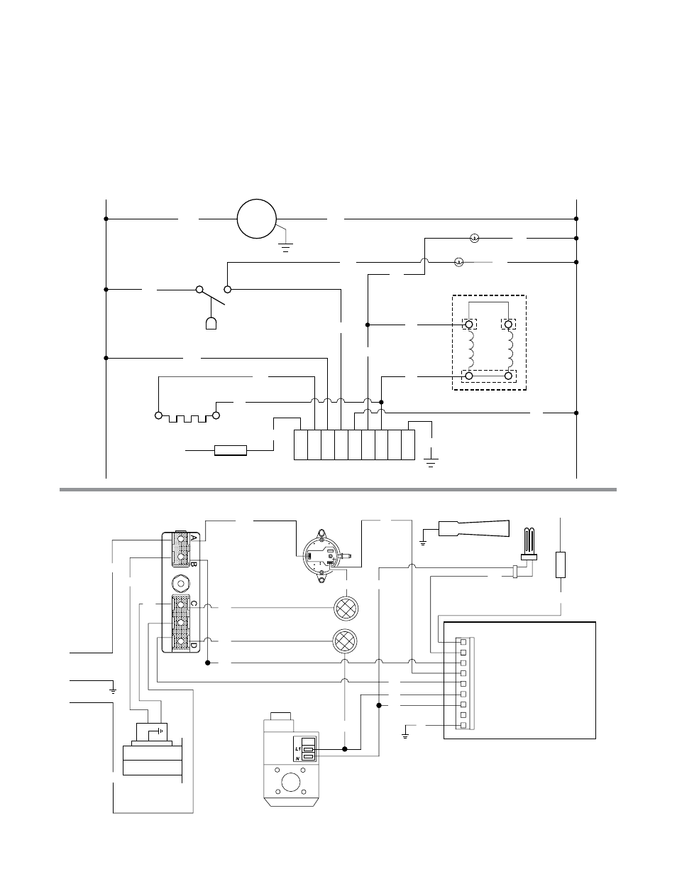
Figure 2.2 • Internal Wiring Diagrams
A. Ladder Diagram - TP-351A
B. Block Diagram - TP-351A
W
R
BK
BK
BK
Ground
Neutral
Valve
Neutral
TH
Line1
SIC1
Probe
W
BK
BK
BK
BK
BK
BR
W
G
120VAC
N
L1
O
BK
W
BK
Terminal Block
Pressure Switch
Indicator Lights
Blower
Burner
Igniter
Flame
Rod
Ignition Module
Gas Valve
SIC1
LINE
1
NEUT
GN
D
NEUT
TH
PROB
E
VALVE
BK
BK
BK
BK
G
BR
W
BK
BK
W
W
N
R
BK
O
BK
BK
120VAC
L1
Blower
Indicator Lights
Pressure Switch
Igniter
Ignition Module
Gas Valve
Flame Rod
BK