Warning, Wiring, Figure 2.1 • field wiring diagrams – Detroit Radiant Products Company SS Series User Manual
Page 7
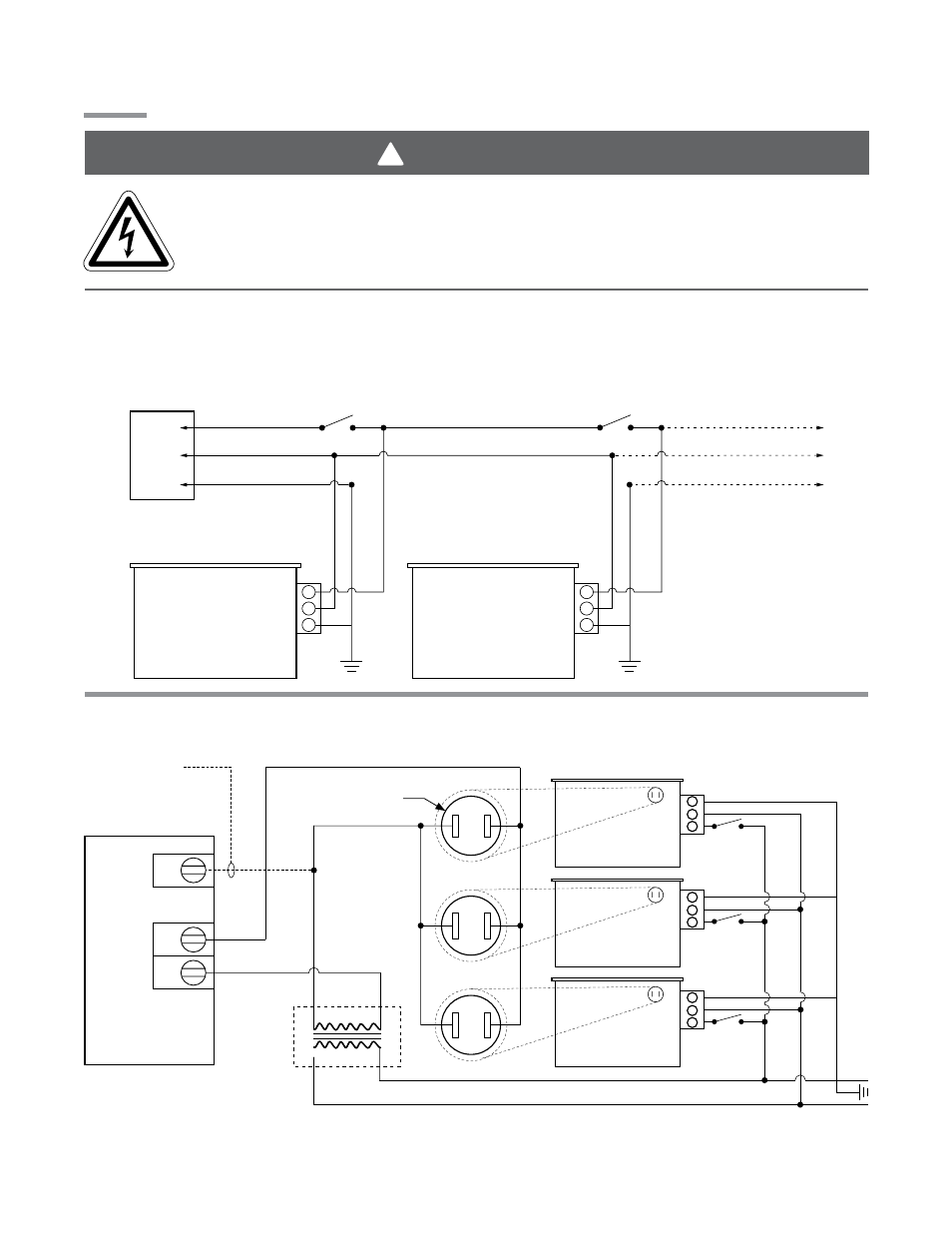
WARNING
!
120VAC-60 Hz.
Supply
NOTE: Up to 4 line voltage tube heaters can
be wired to most thermostats.
L1
Neutral
Ground
Heaters on the same vent
must
share the same thermostat.
Additional heaters
Burner Box
Burner Box
7
2.0
Installation • Wiring
Electric Shock
Field wiring to the tube heater must be connected and grounded in accordance with national,
state, provincial, local codes and to the guidelines in the Tube Heater General Manual and
Series Insert Manual. In the United States refer to the most current revisions to the ANSI/NFPA
70 Standard and in Canada refer to the most current revisions to the CSA C22.1 Part I Standard.
Wiring
DX2
Series
Figure 2.1
•
Field Wiring Diagrams
A. 120VAC Single/Multiple Line Voltage Heater(s)
B. 24VAO (Internal Relay Option)
COM
24V
Burner Control
Box w/ 24VAO
L1
N
120 Volt Power
(Observe polarity)
24VAC Digital
Thermostat
120 VAC
24VAC
Common
W
R
COM
24V
COM
24V
Burner Control
Box w/ 24VAO
Burner Control
Box w/ 24VAO
Common required
for thermostats
that require
constant power.
Common required
for thermostats
that require
constant power.
1/4” spade terminals
required (as supplied)
External
Transformer
(field suppied)