Tube installation sequence – Detroit Radiant Products Company SS Series User Manual
Page 11
11
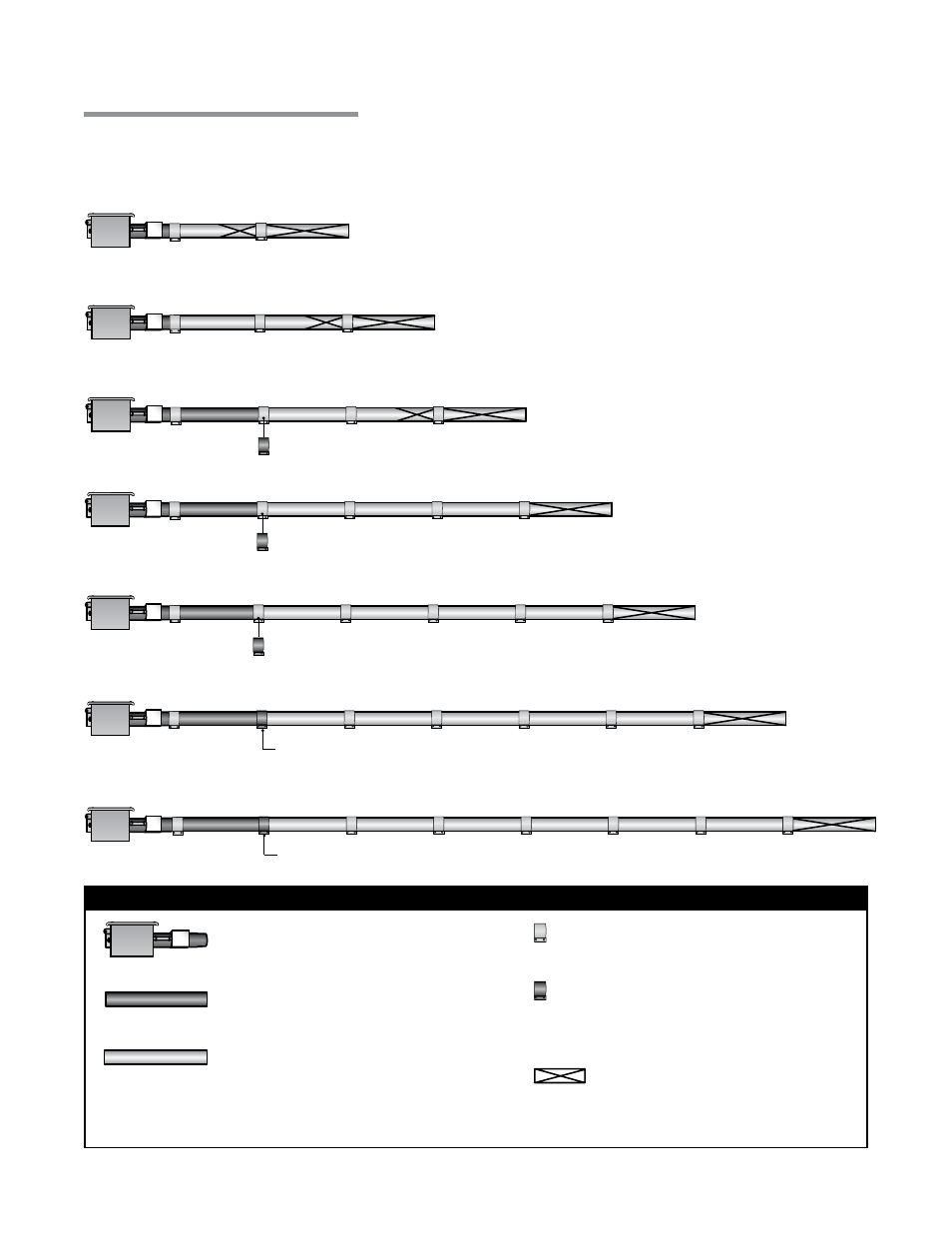
Tube Installation Sequence
20 Foot
50 Foot
60 Foot
70 Foot
30 Foot
40 Foot
Stainless Steel Clamp on 175 - 200 MBH models (P/N: TP-220).
Figure 2.4
•
Tube Installation Sequence
Stainless Steel Clamp on 175 MBH models (P/N: TP-220).
Stainless Steel Clamp Location (P/N: TP-220).
Important! The combustion chamber & radiant tube sections must be installed in the following order.
80 Foot
Stainless Steel Clamp on 175 - 200 MBH models (P/N: TP-220).
Stainless Steel Clamp Location (P/N: TP-220).
Key
Burner Control Box with
16” Burner Tube
Black Coated Combustion
Chamber Tube*
Black Coated Aluminized Combustion
Chamber/Radiant Emitter Tube
Standard Tube Clamp
Stainless Steel Tube
Clamp (P/N: TP-220)
175-200 MBH models only - Located
between 1st and 2nd 10 ft. tube sections.
*Aluminized steel (50,000 to 125,000 BTU/H models), Titanium stabilized aluminized steel (150,000 to 200,000
models).
NOTE: Refer to the Tube Heater General Manual, Chart 3.6 (page 23) for secured reflector joints.
Baffle Location
DX2
Series
2.0
Installation
•
Tube Sequence
•
Heater Length