Detroit Radiant Products Company HL3 Series User Manual
Page 5
5
When installing the tube heater system, clearances to combustibles for the model tube heater and
configuration must be maintained. Refer to Chart 1.1 below to determine the required distances for your model.
The stated clearance to combustibles represents a surface temperature of 90ºF (32ºC) above room
temperature. Building materials with a low heat tolerance (such as plastics, vinyl siding, canvas,
tri-ply, etc.) may be subject to degradation at lower temperatures. It is the installer’s responsibility to
assure that adjacent materials are protected from degradation.
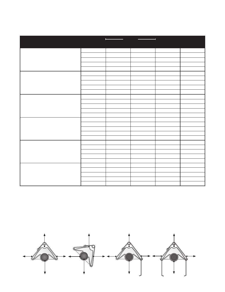
Figure 1.1
•
Mounting Angles
*
Heaters mounted on an angle between 0° to 45° must maintain clearances posted for 0° or 45°; whichever is greater.
45° Mounting Angle
0° Mounting Angle
with 1 Side Shield
(P/N: SSE)
0° Mounting Angle
with 2 Side Shields
(P/N: SSE)
Front
Behind
Below
Top
Front
Behind
Below
Top
Side
Side
Below
Top
0° Mounting Angle
Side
Side
Below
Top
HL3
Series
Model Number
Mounting
Angle*
Sides
Front
Behind
Top
Below
HL3 (20, 30, 40) - (65, 75) [N, P]
0°
9
9
6
60
45°
39
8
10
60
with 1 side shield
0°
29
8
6
60
with 2 side shields
0°
9
9
6
60
20 ft. from burner
0°
7
7
6
30
HL3 (30, 40) - 100 [N, P]
0°
14
14
6
66
45°
39
8
10
66
with 1 side shield
0°
29
8
6
66
with 2 side shields
0°
16
16
6
66
20 ft. from burner
0°
7
7
6
30
HL3 (30, 40, 50) - 125 [N, P]
0°
20
20
6
76
45°
58
8
10
76
with 1 side shield
0°
42
8
6
76
with 2 side shields
0°
20
20
6
76
20 ft. from burner
0°
7
7
6
30
HL3 (40, 50, 60) - 150 [N, P]
0°
24
24
6
81
45°
58
8
10
81
with 1 side shield
0°
42
8
6
81
with 2 side shields
0°
23
23
6
81
20 ft. from burner
0°
11
11
6
44
HL3 (40, 50, 60, 70) - 175 [N, P]
0°
34
34
6
92
45°
63
8
10
92
with 1 side shield
0°
50
8
6
92
with 2 side shields
0°
30
30
6
92
20 ft. from burner
0°
11
11
6
44
HL3 (50, 60, 70) - 200 [N, P]
0°
41
41
6
94
45°
63
8
10
94
with 1 side shield
0°
54
8
6
94
with 2 side shields
0°
30
30
6
94
20 ft. from burner
0°
11
11
6
44
1.0
Safety • Clearance to Combustibles
Chart 1.1 •
Clearance to Combustibles in Inches (see Figure 1.1 for Mounting Angles)