Diagnostics – Detroit Radiant Products Company HL3 Series User Manual
Page 13
13
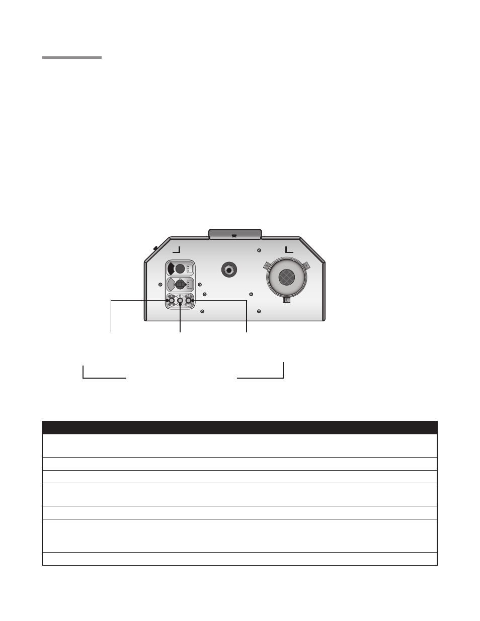
NEUTRAL
EARTH
HOT
- 120V HEATER INPUT -
120V
LOW
NEUTRAL
HIGH
24V
- 24V HEATER INPUT -
HL3
Series
3.0
Operation • Diagnostics
Chart 3.1 •
LED Fault Code Status (located internally on circuit board)
LED Code
Fault Status
Fault Code Delay*
Initial flash on power
up, then steady off
No fault,
normal operation
No delay
Steady ON
Module failure / Internal fault
No delay
1 flash
Ignition failure
3 minutes
2 flashes
APS (Air Proving Switch)
(Fan / Intake / Exhaust)
0 - 30 seconds
3 flashes
Lockout
17 minutes
4 flashes
Solenoid valve fault
Leaky valve
Flame amplifier fault
No delay
No flash on 117V startup
Transformer fault
No delay
*Some LED codes have a time delay before the LED will flash.
Diagnostics
Lockout:
The controls will automatically lockout the heater system when an external or system fault occurs. There
are two types of lockout:
Soft Lockout: The heater will attempt to light three times. In the event of a failed attempt to light, (gas
pressure, valve, no flame sense etc.), the heater will enter a soft lockout period for 15
minutes and then attempt to light three more times before entering Hard Lockout mode.
Hard Lockout: If proof of flame is not established, a component failure occurs or blockages are evident,
the heater will enter hard lockout. If lockout occurs, the control can be reset by briefly
interrupting the power source. Refer to Chart 3.1 below for a description of LED codes.
Figure 3.1
•
Operational Indicator Lights
Light 2 (amber)
Indicates High
Fire Mode
Light 3 (green)
Indicates Pressure
Switch Closes
Light 1 (amber)
Indicates Low
Fire Mode
Operational Indicator Lights