0 operation, Warning, Thermostat – Detroit Radiant Products Company HL3 Series User Manual
Page 12
12
WARNING
!
HL3
Series
3.0
HL3 Series Operation • Sequence of Operation • Thermostat
3.0
Operation
Note: Reference the Tube Heater General Manual for installation requirements.
Sequence of Operation
Standby: The 35-66 control continually checks for internal faults, circuit integrity and relay contact
positioning.
Starting Circuit: Upon a call for heat, the control verifies that the differential switch is in the proper
position (open). The control energizes the fan. Once operational static pressure is achieved, the
differential switch will close initiating the ignition sequence. The glo-bar is powered and the gas valve
opens after 45 seconds. If the flame is not sensed, the heater will attempt to re-ignite for a total of three
(3) trials for ignition before proceeding to soft lockout.
Single Stage Running Circuit: After ignition, the flame rod monitors burner flame. If sense of flame is
lost, the control closes the gas valve within one second and a new trial sequence (identical to the starting
sequence) is initiated. If flame sense is not established within 8.5 seconds, the heater will attempt two (2)
additional ignition sequences before proceeding to soft lockout. The control can be reset by briefly
interrupting the power source.
Two Stage Running Circuit: The second stage on the gas valve is powered directly from the second
stage of the thermostat. In order for two stage to flow to a higher output, single stage must be energized
as well. The thermostat determines which stage to maintain for the desired temperature.
Shut Down: When the thermostat is satisfied, the fan will enter a two (2) minute post-purge cycle. Refer
to Soft and Hard Lockout under Diagnostics; p. 13.
Thermostat
HL3 Series heaters require a 24VAC, two-stage thermostat to operate. The burner control box is equipped
with a round terminal strip that accepts three (3) 1/4” insulated female spade terminals. Do not supply
120V to the 24V connection.
The HL3 Series is equipped with or without relays (P/N: HLRP). The optional relays must be factory
installed.
NOTE: Units with a relay installed must have an external transformer (field supplied), see wiring
diagram. (Figure 2.2B).
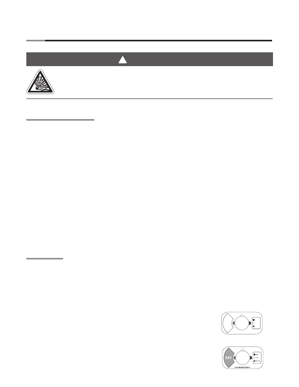
Standard Configuration
Without relays (identified with white label around the terminal block):
• Single burner control box.
• Single thermostat.
Optional Configuration
With relays (identified with orange label around the terminal block):
• A single thermostat controls two or more burner control boxes.
• Heaters are common vented.
• Must be factory installed.
This heater must be installed and serviced by trained gas installation and service
personnel only.
Do not bypass any safety features or the heater’s built in safety mechanisms will be
compromised.
24V
LOW
24V OUT
HIGH
- 24V HEATER OUTPUT -