4 connecting other controllers, Controller 1750n output holder, 24 vdc power – Micromod MOD: 1750N Output holder for MOD 30ML User Manual
Page 14
Output Holder Instructions
POWER, GROUNDING, AND I/O CONNECTIONS
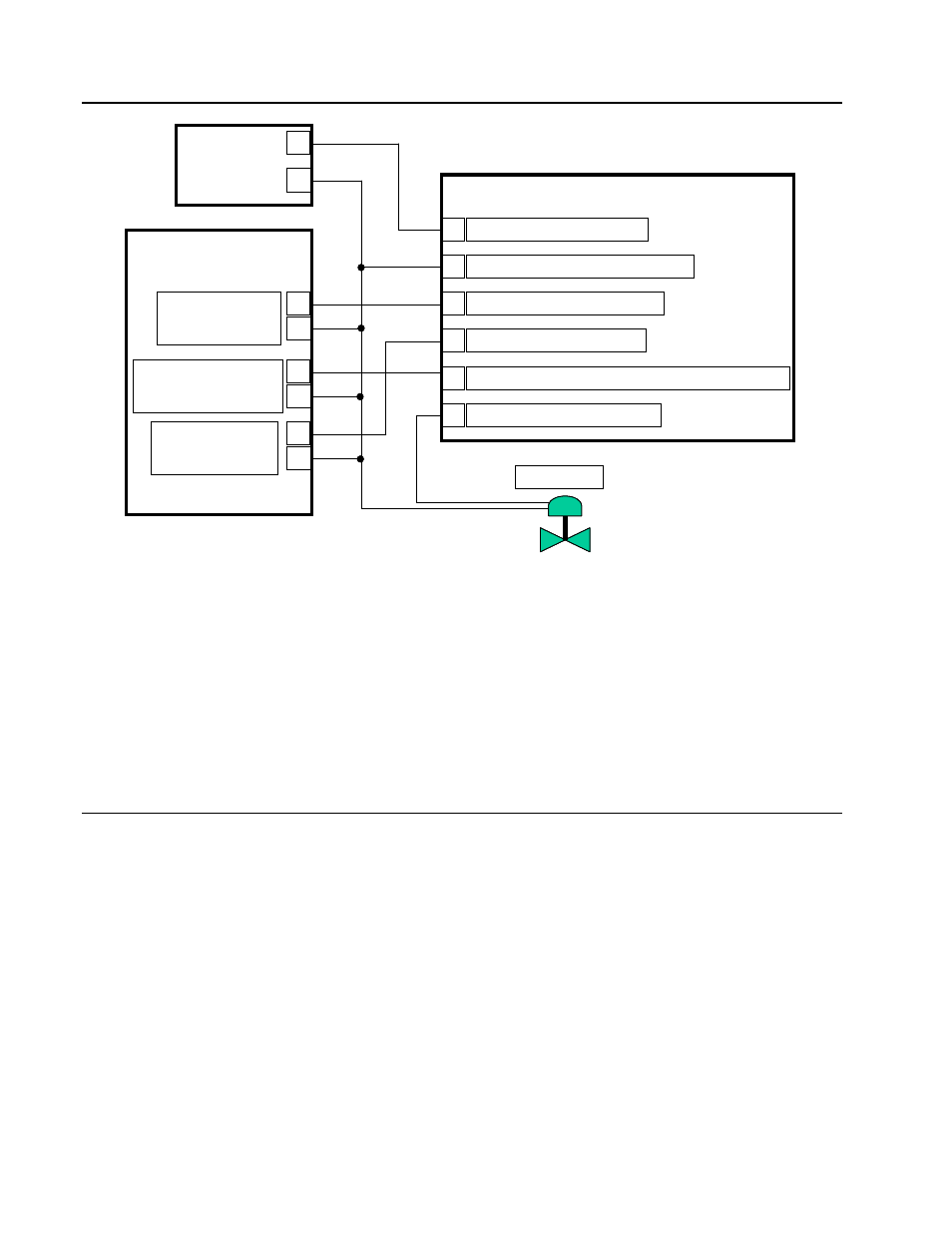
Output
AOUT or 2003A
4-20mA
O.H. Sense Input
2006A
Contact Closure to TCI
Output Track Input
AIN or 2002A
1-5mA to OPTI
Controller
1750N Output Holder
+24 VDC from Power Supply
1
2
3
4
5
6
Power Supply and Signal Commons
4-20mA Output from Controller
1-5mA Monitor to Controller
O.H. Sense to Controller (internally tied to Common)
4-20mA Output to Field Device
24 VDC
Power
–
+
–
–
–
+
+
+
Field Device
The exact wire connections for a particular MOD 30ML Controller or Modcell depends on how
many outputs are being held and where the Sense and Return I/O points for each loop are
located on the controller. For example, if you are using the MOD 30ML controller and if you
are not using the built-in input 2, it may be set up for 1-5 mA non-two wire and used to bring
in the Return signal.
In all cases, the Sense signal will require the installation of a 2006AZ digital input module. It
is also your preference to use or not use the SENSE signal from the output holder. Refer to
chapter 4 for different configuration options with respect to the Sense signal.
3.4
CONNECTING OTHER CONTROLLERS
The output holder can also be used with controllers other than MOD 30ML and Modcell.
Follow the same scheme as given in Figure 3.2.
Use of the Return / Feedback signal (1-5 mA Monitor to controller) and the Output Holder
Sense Discrete signal are optional.
3 -2