Luminex 100 IS 2.2 User Installation Guide User Manual
Page 4
Luminex 100 IS 2.2 User Manual Installation Guide
x
MAP Technology
4
PN 89-00002-00-104 Rev. A
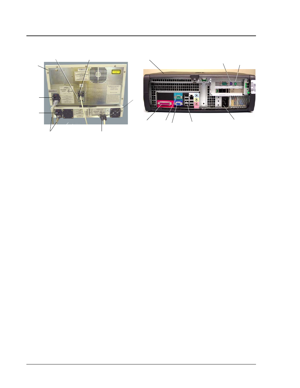
Figure 4 Luminex 100 IS Connections (Luminex 100 analyzer, Luminex XYP Instrument, and PC)
11. Connect the Y-cable to the barcode reader and keyboard, then
connect the Y-cable to the PC. See Figure 5.
12. Plug in only the PC and monitor power cords (disconnects) into
approved outlets with protective earthing only (reference user
manual). We strongly recommend using an uninterruptible power
supply to protect the system from power variations. Refer to
“Protecting Your System” on page 6 for additional information.
13
4
3
7
2
8
6
5
1
14
10
12
16
11
15
9
1. USB Communication Cable (P1)
9. PC
2. Luminex XYP Instrument
10. Y-Cable connection port (PS/2)
3. Luminex XYP Instrument to PC Serial Cable
11. Mouse Cable port (PS/2)
4. Power Cords
12. PC power cable
5. Luminex XYP Instrument Power Switch
13. Luminex 100 port (USB)
6. Luminex 100 Analyzer Power Switch
14. Monitor cable port
7. Luminex 100 analyzer
15. Luminex XYP port
8. Luminex SD CAN bus cable (P2) (identified for
reference)
16. Printer cable port
Note:
Device Disconnects—The
device disconnects for the
Luminex 100 analyzer, the
Luminex XYP instrument, and the
Luminex SD system are the
power cords. Do not position the
100 analyzer, XYP instrument, or
SD system such that it is difficult
operate the disconnect device
(that is remove the power supply
plugs).