Magnum Venus Plastech STAINLESS STEEL CHOP CHECK CCPLS-1000-SS User Manual
Page 5
CHOP CHECK PUMP FLUID SECTION ASSEMBLY
FLUID SECTION ASSEMBLY PROCEDURE:
Displacement Rod Assembly -
1.
Mount the Displacement Rod (CCPLS-1013-SS) in a vise by the wrench flats.
2.
Apply a small amount of Loctite to the threads of the Upper Piston Body (CCPLS-
1011-SS) and thread it into the Displacement Rod (CCPLS-1013-SS).
3.
Insert Ball Check Spring (3102-16-1) into the Upper Piston Body (CCPLS-1011),
larger end first.
4.
Apply a light coat of red grease (6706-2-1) to Piston Ball (9201-2-36) and place it into
the Upper Piston Body (CCPLS-1011-SS), on top of the Ball Check Spring (3102-16-
1).
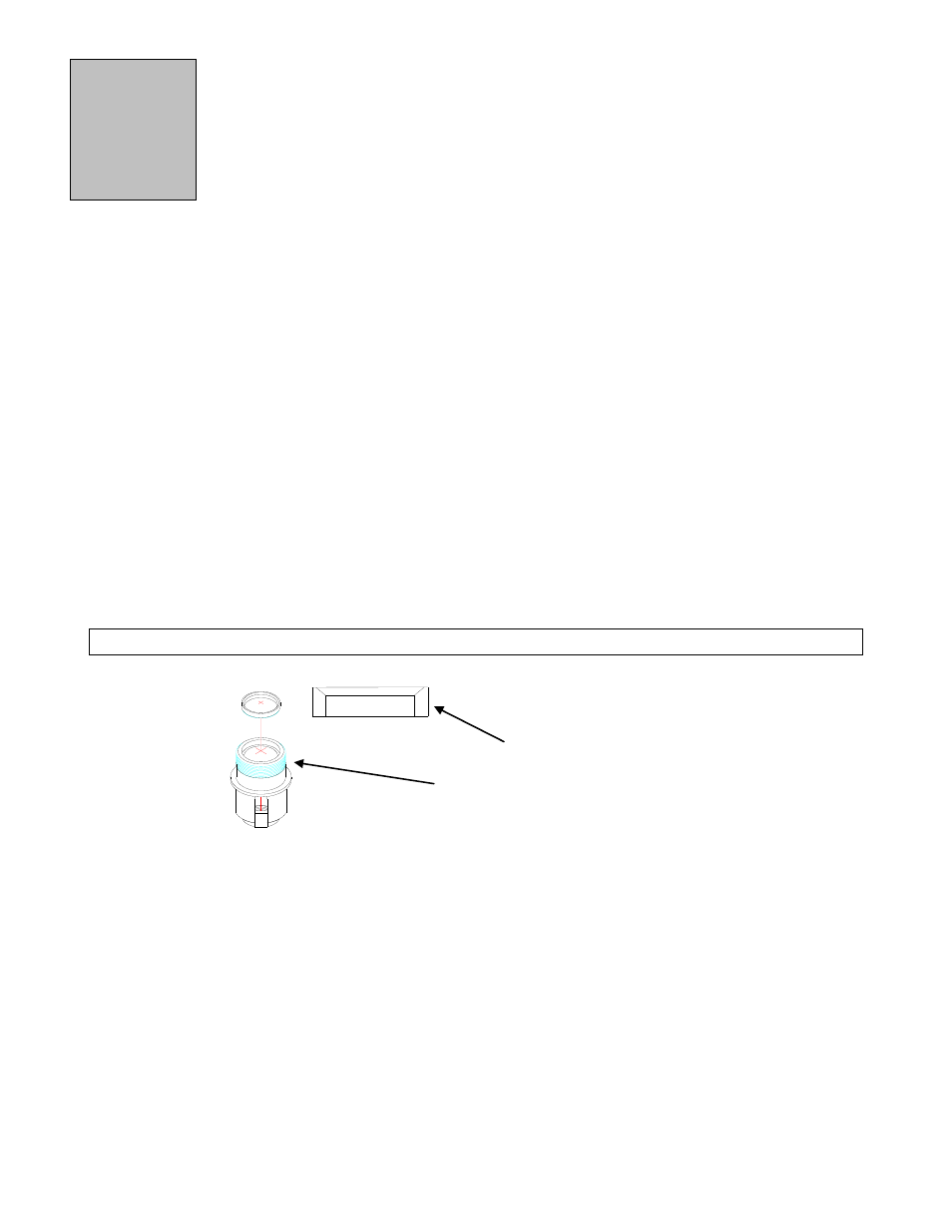
5.
Press Piston Ball Seat (CCPLS-1022-SS) into Lower Piston Body (CCPLS-1012-SS),
with chamfer towards the ball. See below
Note: Use caution not to damage the ball seat area.
6.
Slide Piston Cup Backup Ring (CCPLS-1021-SS) over the lower Piston Body
(CCPLS-1012-SS) ridged side up.
7.
Apply red grease (6706-2-1) into the Piston Cups (CCPLS-1009). Slide one Piston
Cup (CCPLS-1009) with the cup side up over the lower Piston Body (CCPLS-1012-
SS) onto the Piston Cup Backup Ring (CCPLS-1021-SS).
8.
Slide the Piston Cup Spacer (CCPLS-1010-SS) onto the Lower Piston Body (CCPLS-
1012-SS) so that the narrow end is inside the Piston Cup.
9.
Place the other Piston Cup (CCPLS-1009) with the cup side up, over the Lower Piston
Body (CCPLS-1012-SS) down onto the Piston Cup Spacer (CCPLS-1010-SS).
10. Now thread the Lower Piston Body (CCPLS-1012-SS) into the Upper Piston Body
(CCPLS-1011-SS).
Note: Use caution not to over tighten the lower Piston Rod as it will damage the lip of
the piston cups.
CHAPTER
2
PISTON BALL SEAT
– CCPLS-1022-SS
LOWER PISTON BODY
– CCPLS-1012-SS