V-7 valves - installation – Liquid Controls V-7 Valves User Manual
Page 7
7
V-7 Valves - Installation
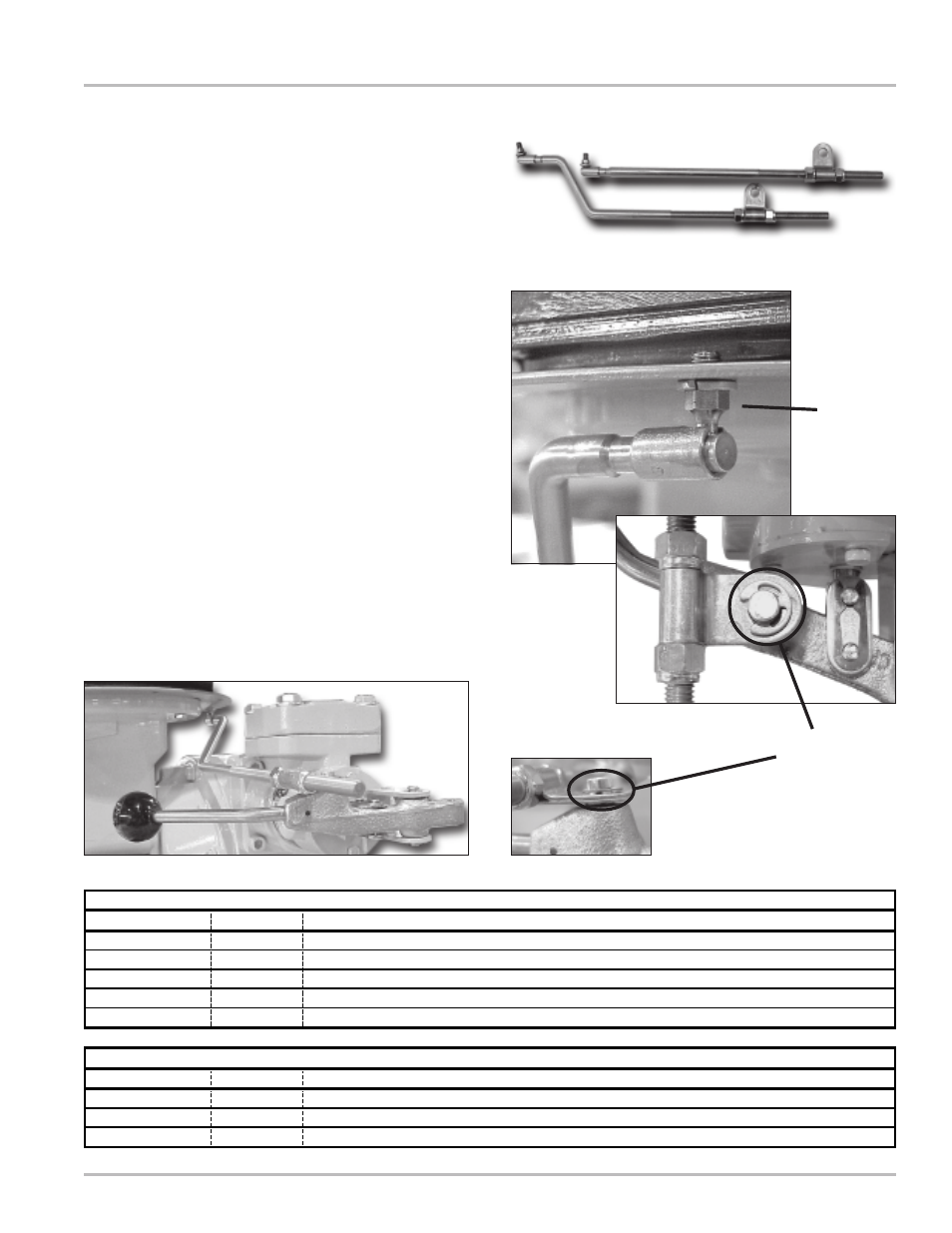
Installing the Linkage Assembly
Linkage assemblies are used with presets. The linkage
provides the connection between the valve handle and
the preset trip ring mounted on the mechanical register.
The linkage assembly is selected based on the meter/
register configuration. Linkage assemblies are available
in either straight or offset styles. These are listed in the
table below.
1. Mount the linkage assembly to the preset ring by
threading the threaded end of the ball joint into the
preset ring. Attach the linkage end to the ball joint
(Figure 13a).
2. Mount the other end of the linkage assembly to the
valve handle. Remove the retaining ring from pivot
stud on the valve handle to accomplish this.
3. Place the linkage bracket over onto the pivot stud
ensuring that the flat side of the linkage bracket is
facing the valve handle (Figures 13b & c). Secure
using the retaining ring.
Proceed with setting the dwell.
Part Number
Style
Description
49925
Offset
For use on M-7 meters with TVC & V-R Preset
A2712
Straight
Linkage Assembly for LC Preset
A2714
Offset
Linkage Assembly for LC Preset
A2728
Offset
Right-to-Left Flow with TVC & LC Preset
A2730
Straight
For all Meters with a Counter Extension & LC Preset
Part Number
Style
Description
49922
Offset
Stainless Steel for use with M-5 & M-7 Meters with V-R Preset
A2725
Straight
Stainless Steel Linkage Assembly for LC Preset
A2726
Offset
Stainless Steel Linkage Assembly for LC Preset
V-7 Valve Linkage Assemblies for Aluminum, Brass, & Cast Iron Valves
V-7 Valve Linkage Assemblies for Stainless Steel Valves
Figure 12: Linkage Assemblies
Figure 13a
Figure 13b
Figure 13c:
Retaining Ring
& Pivot Stud
Figure 13d: Linkage Installed
Ball Joint