V-7 valves - installation, Retrofit installations (continued) – Liquid Controls V-7 Valves User Manual
Page 6
6
V-7 Valves - Installation
Retrofit Installations (continued)
Part Number
Description
43614
Valve Handle Assembly, Curved, Right-to-Left Flow
43617
Valve Handle Assembly, Curved, Left-to-Right Flow
44685
Valve Handle Assembly, Straight
Part Number
Description
46335
Valve Handle Assembly, Straight
45336
Valve Handle Assembly, Curved, Right-to-Left Flow
45337
Valve Handle Assembly, Curved, Left-to-Right Flow
V-7 Valve Handles for Aluminum, Brass, & Cast Iron Valves
V-7 Valve Handles for Stainless Steel Valves
Attaching the Valve Handle
There are several options for valve handles. Systems
which do not use a preset use a faucet valve kit (Part
Number A2755).
For systems which use a preset, curved valve handles
are offered for left-to-right or right-to-left flow, or a straight
handle may be used. The valve handle options are listed
in the table below.
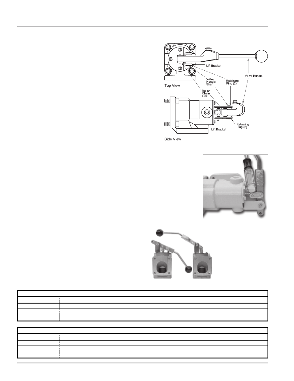
1. Line up the hole in the valve handle with the holes in
the lift bracket.
2. Insert the valve handle shaft through the lift bracket
and valve handle. Secure with one retaining ring on
each side of the lift bracket.
3. Insert the roller chain link into the valve shaft and
valve handle.
4. Slide the flat link over the ends of the roller chain
link. Secure the roller chain link with the retaining
clip.
The valve piston should be flush or slightly drawn into
the valve to ensure proper installation. Use a screwdriver
handle (Figure 10) or a wooden dowel to prop the valve
handle in the open position. This action will compress
the piston spring, drawing the piston into the housing
and allowing the valve to mount flush to the meter. With
the valve propped open, tighten the four bolts in crossing
pattern.
Figure 11 shows the valve handle mounted two different
ways. The valve on the left is opened by pulling on the
handle, the valve to the right by pushing on the handle.
Regardless of the valve or handle orientation, the link
pivot stub must face up in order to properly install the
linkage assembly.
Figure 9: Valve Handle Views
Figure 10: Handle Propped Open
Figure 11: Handle Orientations