Specifications, How v-7 valves work – Liquid Controls V-7 Valves User Manual
Page 3
3
Specifications
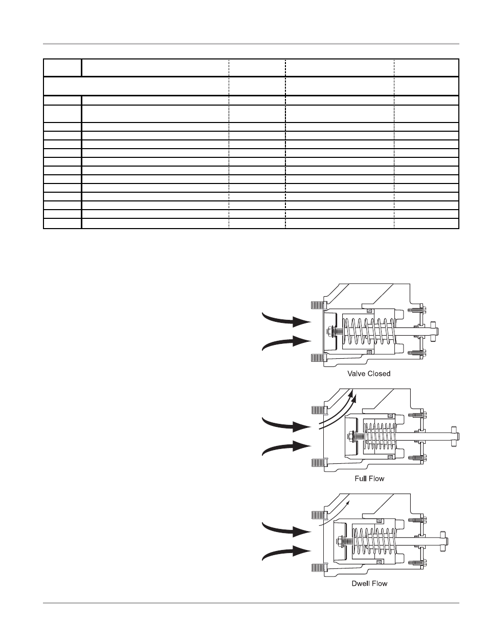
How V-7 Valves Work
Inside the valve housing, a cylindrical bore connects the
valve inlet and outlet. Contained within the bore is a
piston assembly. Measured liquid exiting the meter outlet
is blocked from entering the valve inlet by the piston and
seal.
As the meter operator shifts the handle to the open
position, a mechanical linkage connecting the valve to
the preset counter trip ring causes a latch to engage and
hold the valve open allowing liquid to flow.
In the open position, the valve handle assembly
compresses the piston spring and pulls the piston shaft
and the piston away from the valve inlet. As the piston is
pulled away, it disconnects from the inlet seal, allowing
liquid to flow.
In most metering applications, closing the valve is a two-
stage process. At a predetermined dwell period, the
preset counter, while counting down to “0”, releases a
latch mechanism, allowing the valve linkage to close to
approximately 10% of full flow. This initial closing causes
the piston inside the valve to slide toward the inlet,
restricting product flow.
As liquid is blocked by the piston, some product passes
through the dashpot washer bleed holes, creating the
hydraulic balance feature of V-7 Valves that allows the
valve to close slowly and smoothly. The dwell period
prevents hydraulic shock while permitting the preset
counter to register the remaining flow.
As the preset counter reaches “0”, the preset counter trip
ring disengages from the dwell position to the fully closed
position. This action releases the valve handle and relaxes
the piston spring, permitting the piston to contact the inlet
ring seal and complete its closure, stopping product flow.
This process is illustrated in Figure 2.
Model
Companion
Flanges
Application
Class*
A2621
1½" & 2"
1, 2, 14
A2623
1½" & 2"
1, 2, 3, 4, 14, 15,
16, 30
A2631
1½" & 2"
1, 3, 14, 15
A2651
1½" & 2"
3, 4, 14, 15, 16
A2652
1½" & 2"
1, 2, 16, 20
A2655
1½" & 2"
1, 30
A2684
1½" & 2"
20
A2690
1½" & 2"
20
A2693
1½" & 2"
20
A2670
1½" & 2"
7, 37
A2671
1½" & 2"
7, 27
A2672
1½" & 2"
7, 27, 37
A2681
1½" & 2"
8
A2682
1½" & 2"
8
150 PSI (10.3 BAR)
150 PSI (10.3 BAR)
150 PSI (10.3 BAR)
150 PSI (10.3 BAR)
150 PSI (10.3 BAR)
150 PSI (10.3 BAR)
150 PSI (10.3 BAR)
150 PSI (10.3 BAR)
150 PSI (10.3 BAR)
150 PSI (10.3 BAR)
150 PSI (10.3 BAR)
150 PSI
(10.3 BAR)
150 PSI (10.3 BAR)
150 PSI (10.3 BAR)
150 PSI (10.3 BAR)
V-7 (A2600 Series)
Used with M-5, M-7 & M-10 Meters
Body & Seal Material
Cast Iron with Viton Seal
Stainless Steel with Viton Seal
Stainless Steel with Teflon Seal
Brass with Teflon Seal
Cast Iron with Viton Seal
Cast Iron with Teflon Seal
Aluminum with Viton & Teflon Seal
Brass with Viton Seal
Brass with Viton Seal
Aluminum with Viton Seal
Aluminum with Teflon Seal
Aluminum with Viton Seal
Aluminum with Viton Seal
Aluminum with Buna N Seal
Working
Pressure
Figure 2: Valve Operation