Hardware installation, Installing/removing receiver modules, Rack installation – Lectrosonics Venue 3.9 User Manual
Page 6: Installing receiver modules, Removing receiver modules, Venue, Front panel, Lectrosonics, inc
IN
USB
IN
OUT
OUT
1
2
1
2
1
2
10.5-18VDC
ANTENNA A
ANTENNA B
1
2
1
2
1
2
RS-232
6
5
4
3
3
3
3
2
1
3
3
3
Venue
Hardware Installation
Installing/Removing Receiver Modules
VRS and VRT receiver modules can be mixed in one
VRM chassis, For ratio diversity operation, both mod
ules in the pair must be on the same frequency block
and positioned in the assembly in keeping with the
labeling on top of the chassis housing.
Front panel
With the 50 MHz bandwidth version, all modules must
also be within the passband of the VRM assembly fre
quency blocks are marked on the housings.
Installing Receiver Modules
1. Turn the power off first.
The receiver modules interface with the main as
sembly through multi-pin connectors on either side
of the chassis. Insert the module straight down and
then slide it toward the main housing to insert the
connector pins. The module should sit flush against
the side of the housing.
Rack Installation
The Venue Receiver is designed for standard rack
mount installation. Each VRM chassis occupies a single
rack space.
1. Physically install the VRM(s) in the desired
location(s). There are no special ventilation require
ments.
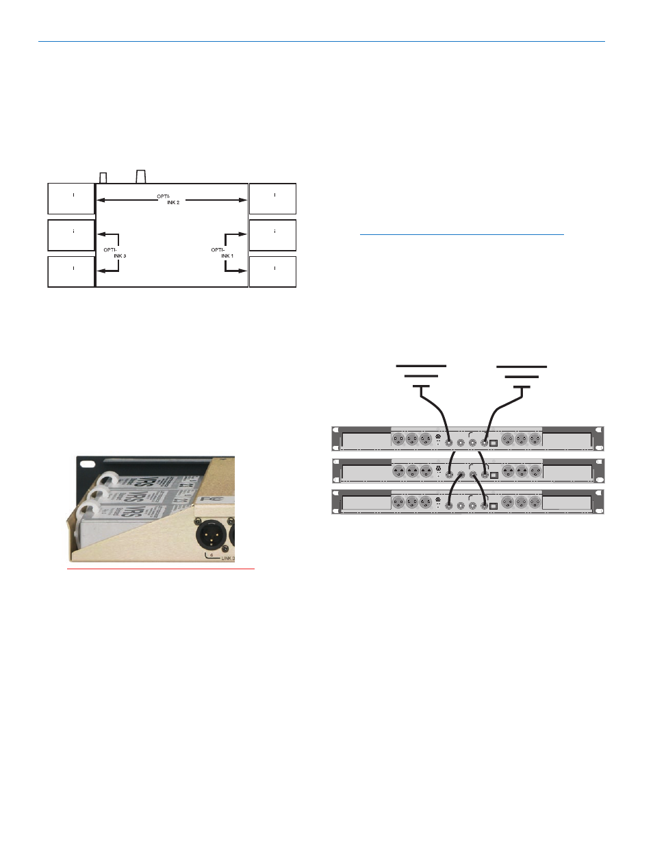
2. Connect the antennas or coaxial cables to the
antenna input connectors (outermost) on the rear
panel of the VRM.
Note: The frequency bandwidth of the antennas
must cover the range of the modules in use.
3. For multiple unit installations, connect coaxial
cables from the antenna outputs the first VRM to
the antenna inputs on the next unit in the stack.
The outermost connectors are the inputs connected
to the antennas on the first unit in the stack. The
innermost connectors are the outputs that feed the
next assembly in the rack.
LINK 2
LINK 3
10.5-18VDC
RS-232
6
5
4
LINK 2
3
2
1
IN
USB
IN
OUT
OUT
ANTENNA A
LINK 1
LINK 3
1
3
2
1
3
2
1
3
2
ANTENNA B
1
3
2
1
3
2
1
3
2
Caution: Make sure the connectors align
correctly. Do not force the module onto the tab.
Excessive force may damage the connectors.
2. Align the ridge on the retaining clip with the slot in
the chassis and press the clip downward until the
ridge snaps into the slot on the chassis.
Removing Receiver Modules
1. Turn the power off first.
2. Remove the retaining clips by pressing sideways to
rotate the clip until it releases from the slot in the
metal side panel. Then pull upward to remove it.
3. Pull outward on the module to release the connec
tor and then lift it upward out of the chassis. Holes
in the underside of the chassis allow you to grip the
module on the top and bottom.
LINK 1
LINK 3
LINK 2
4. Plug the VR power supply into a suitable outlet and
plug the power connector into the Power Input Jack.
Repeat for each Venue System being installed.
5. Turn down the audio inputs on all the externally
connected equipment, then connect them to the ap
propriate Audio Output XLR Jacks.
6. If the Venue System is to be set up using a com
puter system using a USB interface, connect a USB
cable between the USB connector on the rear panel
of the VRM and the computer system or a USB hub
connected to the computer system.
7. Refer to “Setting Up the Venue System via the USB
Port.”
LINK 1
LECTROSONICS, INC.
IN
USB
IN
OUT
OUT
1
2
1
2
1
2
10.5-18VDC
ANTENNA A
ANTENNA B
1
2
1
2
1
2
RS-232
6
5
4
3
3
3
3
2
1
3
3
3
6