Antenna use and placement, Phantom power – Lectrosonics Venue 3.9 User Manual
Page 21
Digital Hybrid Wireless™ Modular Receiver System
Antenna Use and Placement
The Venue System is designed for rack mounting.
Although it can be operated with two whip antennas, it
is best to use remote antennas such as the SNA600
or ALP700 for optimum reception. Position the remote
antennas at least three or four feet apart and not within
three or four feet of large metal surfaces. If this is not
possible, try to position the antennas so that they are as
far away from the metal surface as is practical. It is also
good to position them so that there is a direct “line of
sight” between the transmitter and the receiver anten
nas.
In situations where the operating range is less than
about 100 feet, the antenna positioning is much less
critical. However, the length of the cabling between
antennas and the system is critical. Long cable runs
can experience serious signal loss. Lectrosonics offers
in-line RF amplifiers suitable for compensating for this
signal loss. Contact your dealer or the factory for more
information.
A wireless transmitter sends a radio signal out in all
directions. This signal will often bounce off nearby walls,
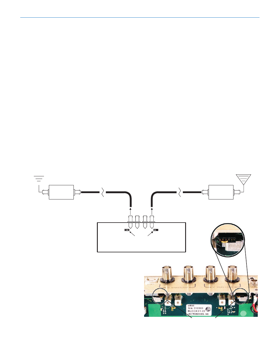
Phantom Power
An tenna
UFM230
Long coax cabl e
DC Power to UFM230
Remote antennas can be placed
at a distance from the VRM to
optimize reception. To overcome
loss in long coaxial cable runs, a
Lectrosonics UFM Series inline
RF filter/amp should be positioned
at the far end of the coaxial cable,
close to the antenna.
With amplifier in this position, gain is applied ahead
of the loss to maximize the signal to noise ratio of the
antenna system.
Power for the UFM amplifier can be supplied by the
VRM assembly through the coaxial cable by setting
jumpers on the main PC board toward the center of the
board as shown. Disconnect power from the VRM, then
remove the top cover for access to the jumpers.
NOTE: It is best practice to enable this DC power ONLY
when a UFM remote amplifier is used. Some anten
nas may present a short to the power supply. While the
power supply is fused and it is unlikely that damage
would occur to the VRM, it is always best to disable the
DC when it is not in use.
VRM
Jumpers set
towards the center
Location of Jumpers
ceilings, etc. and a strong reflection can arrive at the
receiver’s antennas along with the direct signal. If the
direct and reflected signals are out of phase with each
other and similar in strength, a cancellation (“dropout”)
may occur. A dropout can sound like audible noise
(hiss or swishing), or in severe cases, it may result in a
complete loss of both the carrier and the sound. Moving
the transmitter even a few inches will change the sound
of the dropout, or may even eliminate it. A dropout situa
tion also may be either better or worse as a crowd fills
or leaves the room.
The Venue System offers a several sophisticated diver
sity designs which can overcome most dropout prob
lems. In the event, however, that you do encounter a
dropout problem, first try moving the one of the remote
antennas at least three or four feet from its current
location. This may alleviate the dropout problem at that
location. If dropouts are still a problem, try moving the
antennas to entirely different locations.
Lectrosonics transmitters radiate power very efficiently,
and the receivers are very sensitive. This reduces
dropouts to an insignificant level. If, however, you do en
counter dropouts frequently, call the factory or consult
your dealer. There is probably a simple solution.
An tenna
Long coax cabl e
UFM230
DC Power to UFM230
Jumper positioned to
enable DC power
Rio Rancho, NM
21