Rear panel, Rear panel features, Power input jack – Lectrosonics Venue 3.9 User Manual
Page 5: Receiver modules, Xlr audio output jacks, Serial port, Antenna input jacks, Multicoupler (antenna) output jacks, Usb port
Rear Panel
Digital Hybrid Wireless™ Modular Receiver System
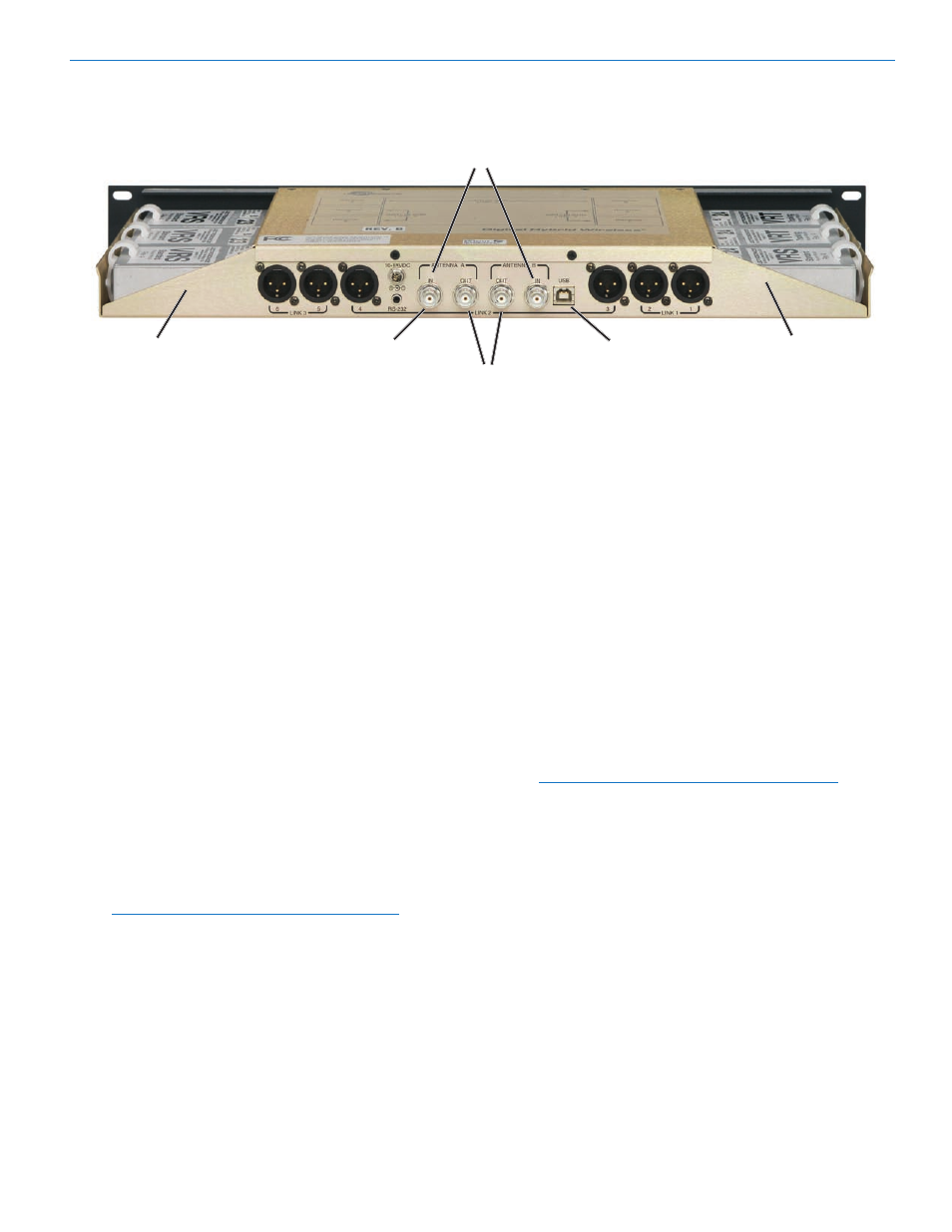
Antenna Inputs
Receiver
Receiver
Modules 4-6
RS-232
USB Port
Modules 1-3
Port
Multicoupler Outputs
Rear Panel Features
The rear panel provides six balanced XLR audio out
puts, two 50 Ohm BNC antenna inputs, two 50 Ohm
BNC antenna outputs from an internal multicoupler, a
power jack with a locking connector, with USB and RS
232 serial ports for setup and control.
Power Input Jack
The power input jack accepts +10 VDC to +18 VDC
(center pin is positive and sleeve is ground). The input
is diode protected to prevent damage if the power is ac
cidentally applied with reversed polarity. The unit will not
operate until the correct polarity is restored.
Receiver Modules
Up to six receiver modules in two rows of three can be
installed in each VRM. Spring loaded Receiver Module
Retainer Clips ensure module connections are main
tained during transport and installation.
XLR Audio Output Jacks
Six balanced XLR audio output jacks connect the
Venue System to external equipment. The default value
for receiver audio output is XLR pin 2 “in phase” with
regard to the audio signal from the transmitter. This can
be reversed for each receiver using the LCD or control
software.
Note: Audio phase is reversed by some wiring
schemes for lavalier microphones on belt pack
transmitters.
Serial Port
A serial RS-232 interface is provided for setup and
control of the Venue System from computers or other
devices using industry standard RS-232 communication
links.
Antenna Input Jacks
Two BNC input connectors are provided for right-angle
whip antennas, cables from remote antennas, or cables
from another VRM. An internal mulitcoupler ensures the
RF is applied equally to all installed Receiver Modules
and also to the Antenna Output Jacks.
Multicoupler (antenna) Output Jacks
The built-in antenna multicoupler provides RF distribu
tion for the six receiver modules and a “loop thru” output
to deliver the RF to another Venue receiver. The sec
ond receiver can then feed a third receiver to create a
“stack” that operates with a single pair of antennas. The
result is very efficient use of rack space.
Note: Venue receivers with a 50 MHz bandwidth
must be on the same frequency blocks to use the
antenna loop through.
USB Port
Standard USB Version 1.1 port for setup and control of
the VRM from computer systems using Windows
®
2000,
XP or Vista.
Rio Rancho, NM
5