Laurel Electronics LTE SERIES TRANSMITTERS ANALOG INPUT User Manual
Page 23
- 23 -
14. RTD & OHMS SIGNAL CONDITIONER BOARD JUMPER SETTINGS
The standard RTD and resistance signal conditioner board can be configured via jumpers for
four RTD types (DIN 100Ω platinum, ANSI 100Ω platinum, 120Ω nickel, 10Ω copper) or five
resistance ranges (from 20.000Ω to 200.00 kΩ). A fixed 2 MΩ resistance range (R6 ordering
option) is provided by a factory modified signal conditioner board with component changes.
All ranges are factory calibrated with calibration factors stored in EEPROM on the signal condi-
tioner board. Instrument Setup Software recognizes the board and will bring up the appropriate
menu items for it; however, it does not recognize the jumper settings. With RTDs, display in °C
or °F and resolution of 1°, 0.1° or 0.01° are user programmable.
1. Use 2.5 mm (0.1") jumpers.
2. Store spare jumpers on an unused jumper post.
PROVISIONS FOR LEAD WIRE RESISTANCE
RTD and resistance measurement allow 2-, 3- or 4-wire hookup to compensate for lead wire
resistance. Please see Section 6 for hookup diagrams.
•
In 2-wire hookup, the transmitter senses the voltage drop across the load and both lead
wires. The effect of the lead wires can be measured and subtracted by shorting out the load
during transmitter setup, as prompted by Instrument Setup software. The short should be as
close as possible to the load. Ambient temperature changes will still cause some error in the
readings -- the higher the lead resistance, the greater the error.
•
In 3-wire hookup, the transmitter automatically compensates for lead resistance by mea-
suring the voltage drop in one current-carrying lead and assuming that the voltage drop in
the other current-carrying lead is the same.
•
In 4-wire hookup, there is no lead wire resistance error, as different pairs of wires are used
for excitation and sensing. The sense wires only carry a few picoamperes and hence can
measure the voltage across the RTD without error.
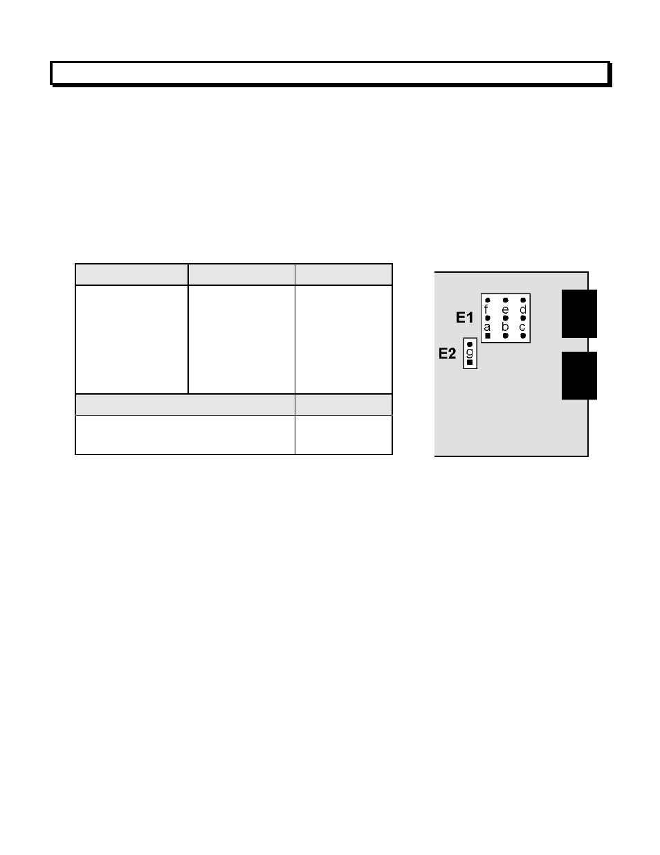
Standard Board
Modified Board
E1 Jumper
Pt100, Ni120
Cu10, 20.000
0 - 200.00Ω
0 - 2.0000 kΩ
0 - 20.000 kΩ
0 - 200.00 kΩ
N/A
N/A
N/A
N/A
N/A
0 - 2.0000 MΩ
a
b
c
d
e
f
Connection
E2 Jumper
2 or 4 wire
3 wire
none
g