Installation, Headers e3 and e4 – Impulse 3087 User Manual
Page 8
Card Setup
Sealevel Systems COMM+2/EX Page
5
Set the jumper to ‘S’ if using more than one COMM+2/EX in a bus or to completely remove the pull-down resistor
for hardware compatibility. Setting the adapter in this configuration when it is not accompanied by a pull-down
resistor will prevent the ports from triggering an interrupt.
E1
0
E9
N S M
N S M
Figure 6 - Headers E9 and E10, Sharing IRQ’s with another adapter
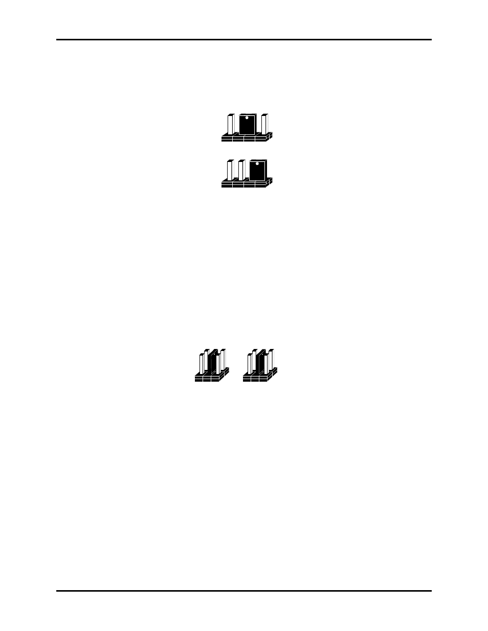
Headers E3 and E4
Position ‘A’ Determines whether the RS-485 driver is enabled by the UART signal Request To Send (RTS) or
always enabled. With the jumper installed in position ‘A’, RTS enables the driver. Removing the jumper enables the
driver regardless of RTS. E4 sets Port 1 while E3 sets Port 2. This jumper should only be set to ‘A’ if you are
running the board in a multi-drop polled environment such as RS-485, and you have software that ‘knows how to
talk’ on the RS-485 bus. For normal point-to-point RS-422 (such as terminal emulation), make sure that a jumper at
position ‘A’ is not in place.
Positions ‘B’ & ‘C’ determine whether the board provides a direct ground connection (as in RS-232 and most RS-
422), or a 100 ohm high impedance ground. The high impedance ground is normally used by RS-485 (and some RS-
422) to avoid ground loop currents with long cables. Position ‘B’ selects the direct ground and position ‘C’ selects
the 100 ohm high impedance ground.
A B C
A B C
Figure 7 - Headers E3 and E4 (Factory Default