Impulse 3093 User Manual
Page 13
© Sealevel Systems, Inc.
- 11 -
DIO-32B User Manual
Relative Addressing vs. Absolute Addressing
The SeaIO API makes a distinction between “absolute” and “relative” addressing
modes. In absolute addressing mode, the Port argument to the API function acts as a
simple byte offset from the base I/O address of the device. For instance, Port #0
refers to the I/O address base + 0; Port #1 refers to the I/O address base + 1.
Relative addressing mode, on the other hand, refers to input and output ports in a
logical fashion. With a Port argument of 0 and an API function meant to output
data, the first (0
th
) output port on the device will be utilized. Likewise, with a Port
argument of 0 and an API function designed to input data, the first (0
th
) input port of
the device will be utilized.
In all addressing modes, port numbers are zero-indexed; that is, the first port is port
#0, the second port is #1, the third #2, and so on.
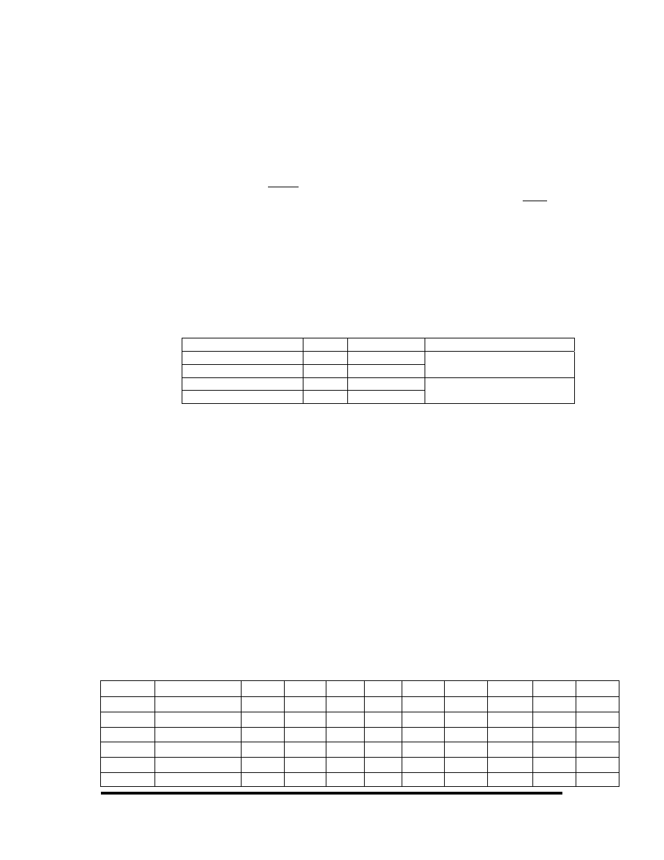
Direct Hardware Control
In systems where the users program has direct access to the hardware (DOS) the
tables that follow give the mapping and functions that the DIO-32B provides.
Function Available
Port
Address Hex
Port Type
RD
A
Base + 0
RD
B
Base + 1
Optically Isolated Input Port
RD/WR
C
Base + 2
RD/WR
D
Base + 3
Reed Relay Output Port
RD = Read, RD/WR = Read or Write
Reading the Inputs
The inputs are active Low. If no voltage is applied across one of the differential
inputs it returns a one on that bit. If an AC or DC voltage is applied it returns a zero
on that bit.
Reading the Outputs
The relay ports return the ones complement of the value that is currently being used
to drive the relays.
Writing the Outputs
The output ports are the only ports that can be written. The relays on a standard
DIO-32B are normally open. To close a relay a one must be written to the
appropriate bit.
Register Description
All ports are set to input after reset or power up.
Address Mode
D7
D6
D5
D4
D3
D2
D1
D0
Base+0
Input Port A
RD
PAD7 PAD6 PAD5
PAD4
PAD3
PAD2
PAD1
PAD0
Base+1
Input Port B
RD
PBD7 PBD6 PBD5
PBD4
PBD3
PBD2
PBD1
PBD0
Base+2
Output Port C
RD/WR PCD7 PCD6 PCD5
PCD4
PCD3
PCD2
PCD1
PCD0
Base+3
Output Port D
RD/WR PDD7 PDD6 PDD5
PDD4
PDD3
PDD2
PDD1
PDD0
Base+4
RD
0
0
0
0
0
0
0
0
Base+5
Interrupt Status RD/WR IRQEN IRQST
0
0
0
0
IRC1
IRC0