Technical description – Impulse SIO-104+2 (3502) User Manual
Page 10
Technical Description
Sealevel Systems SIO-104+2 Page
8
Technical Description
The SIO-104+2 series provides the ultimate serial connection for your PC/104 application. SIO-104+2 utilizes the
16850 UART. These chip features programmable baud rates, data format, interrupt control and 128 Byte input and
output FIFOs.
The SIO-104+2 when configured with the RS-422/485 interface will allow long length, high-speed communications
suitable for data collection and shop floor control.
The SIO-104+2 when configured with the RS-232C interface, is fully compatible with the DOS operating system,
all popular modem software, network operating systems software, and mouse drivers.
Features
• Selectable interrupts (IRQs) 3, 4, 5, 7, 9, 10, 11, 12, 15
• Multiple adapters can share the same IRQ
• Uses PC/104 compatible stack through connector for universal mounting
• 5 volt only DC operation
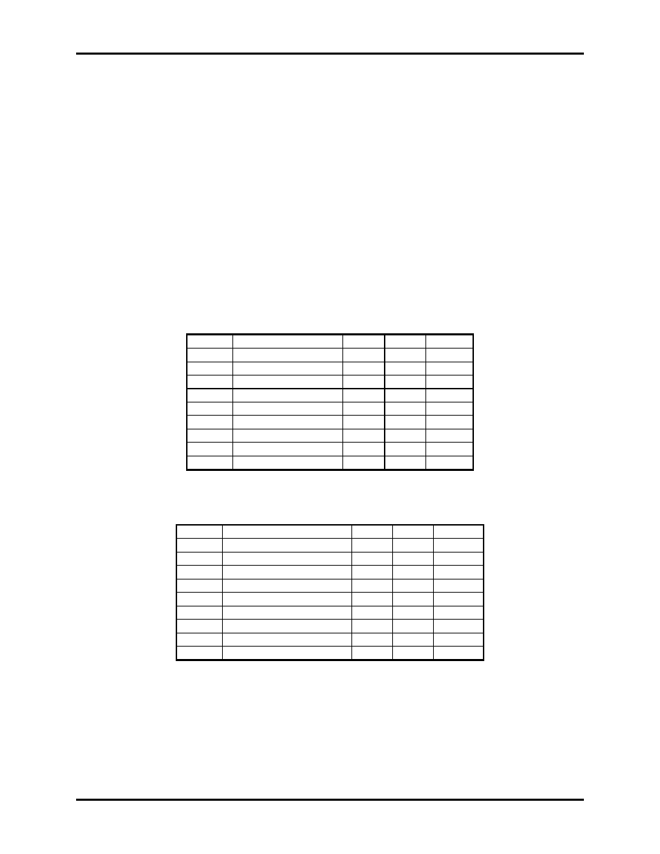
Connector Pin Assignments
RS-232
Signal Name J1/J2
DB-9
Mode
GND Ground
9
5
TD Transmit
Data
5 3
Output
RTS
Request To Send
4
7
Output
DTR
Data Terminal Ready
7
4
Output
RD Receive
Data
3 2 Input
CTS
Clear To Send
6
8
Input
DSR
Data Set Ready
2
6
Input
CD Carrier
Detect
1 1 Input
RI Ring
Indicator
8 9
Input
Note: These assignments meet EIA/TIA/ANSI-574 DTE for DB-9 type connectors.
RS-422/485
Signal Name
Pin
#
Mode
GND Ground
9
5
TX +
Transmit Data Positive
7
4
Output
TX-
Transmit Data Negative
5
3
Output
RTS+
Request to Send Positive
2
6
Output
RTS-
Request to Send Negative
4
7
Output
RX+
Receive Data Positive
1
1
Input
RX-
Receive Data Negative
3
2
Input
CTS+
Clear to Send Positive
8
9
Input
CTS-
Clear to Send Negative
6
8
Input
Technical Note: Please terminate any control signals that are not going to be used. The most common way to do this
is connect RTS to CTS and RI. Also, connect DCD to DTR and DSR. Terminating these pins, if not used, will help
insure you get the best performance from your adapter.