Controlled Products Systems Group 212ILMBZ User Manual
Page 5
6051344 Rev. 1.0
Page 5 of 17
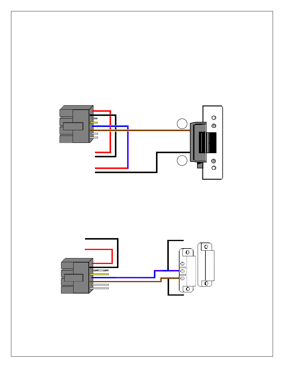
Situation 2:
If you are using a separate power supply with the 212iLM Mullion and the Electric Strike, you need to run
voltage from the positive of the power supply to the Brown (normally open) wire on the 8 conductor wire
harness of the 212iLM.
Step 1: Connect the Positive (red) wire on the 212iLM Mullion harness to Positive voltage coming from
the 212iLM power supply.
Step 2: Connect the Negative voltage wire on the 212iLM power supply to the Negative (black) voltage
wire on the 212iLM power supply.
Step 3: Connect the Brown (normally open) on the harness to the positive connection on Electric Strike.
Step 4: Connect the Blue (common) wire from the 212iLM harness to the Positive voltage on the lock
power supply.
Step 5: Connect the Negative voltage coming from the lock power supply to the Negative connection on
the Electric Strike.
Example of Wiring to an Electric Strike Using a SEPARATE Power Supply:
Shunting a Normally Closed Zone: (see below)
Step 1: Connect the Blue (Common) Relay wire from the 212iLM Mullion harness to the Common
connection on the door position switch.
Step 2: Connect the Brown (Normally Open) Relay wire from the 212iLM Mullion harness to the Normally
closed connection on the Door position switch.
Example of Shunting a Normally Closed Zone
Red
Black
To Power Supply V-
To Power Supply V+
Blue = Common
Brown = Normally open
Red
Black
212iLM
Wire
Harness
Blue = Common
Brown = Normally
open
_
+
212iLM
Wire
Harness
To 212iLM V+
Power Supply V-
To Lock V+
Power Supply V-